1.12
EARTH GROUNDING PROCEDURE
1. Customer to provide and install a ground rod approx. 0.60 (15mm) diameter, copper clad steel, to be driven no
less than 8’ (2.5m) into the ground, no more than 10’ (3m) away from control enclosure.
2. Ground rod to be connected to customer’s in plant ground system. This connection shall be made directly at the
ground rod (if applicable).
3. It is desirable that the overall resistance to ground measured at the ground rod does not exceed 3 ohms. Cus-
tomer is advised to consult local power company for further information on grounding.
4. Ground rod to be connected to ground terminal in control enclosure using insulated, 8 AWG stranded copper wire.
The correct wire size is shown.
An additional point to check is ensuring continuity of ground within control enclosure. Start with main power entrance
ground terminal where internal ground conductors should originate and connect to, DIN terminal strip, control transformer
and the lid of control enclosure. Also PLC and Interface units should have their own ground conductors connected to one
of the main ground terminals.
Properly functioning ground system will;
• Provide safety for personnel.
• Ensure correct operation of electrical/electronic devices.
• Prevent damage to electrical/electronic apparatus.
• Help dissipate lightning strokes.
• Divert stray radio frequency (RF) energy from electronic/control equipment.
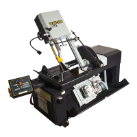
BLADE TENSION CHECK
When the machine is rst started, the head must be swung to the vertical position so the blade position can be checked.
Open the door at the top of the head and see that the blade has not moved o of the wheel. It should not be overhanging
from the wheel more that 1/4”, if it is, then consult Blade Tracking information. If it has stayed in its correct position, then
turn the blade tension switch to the “+” and close the door.