2.21
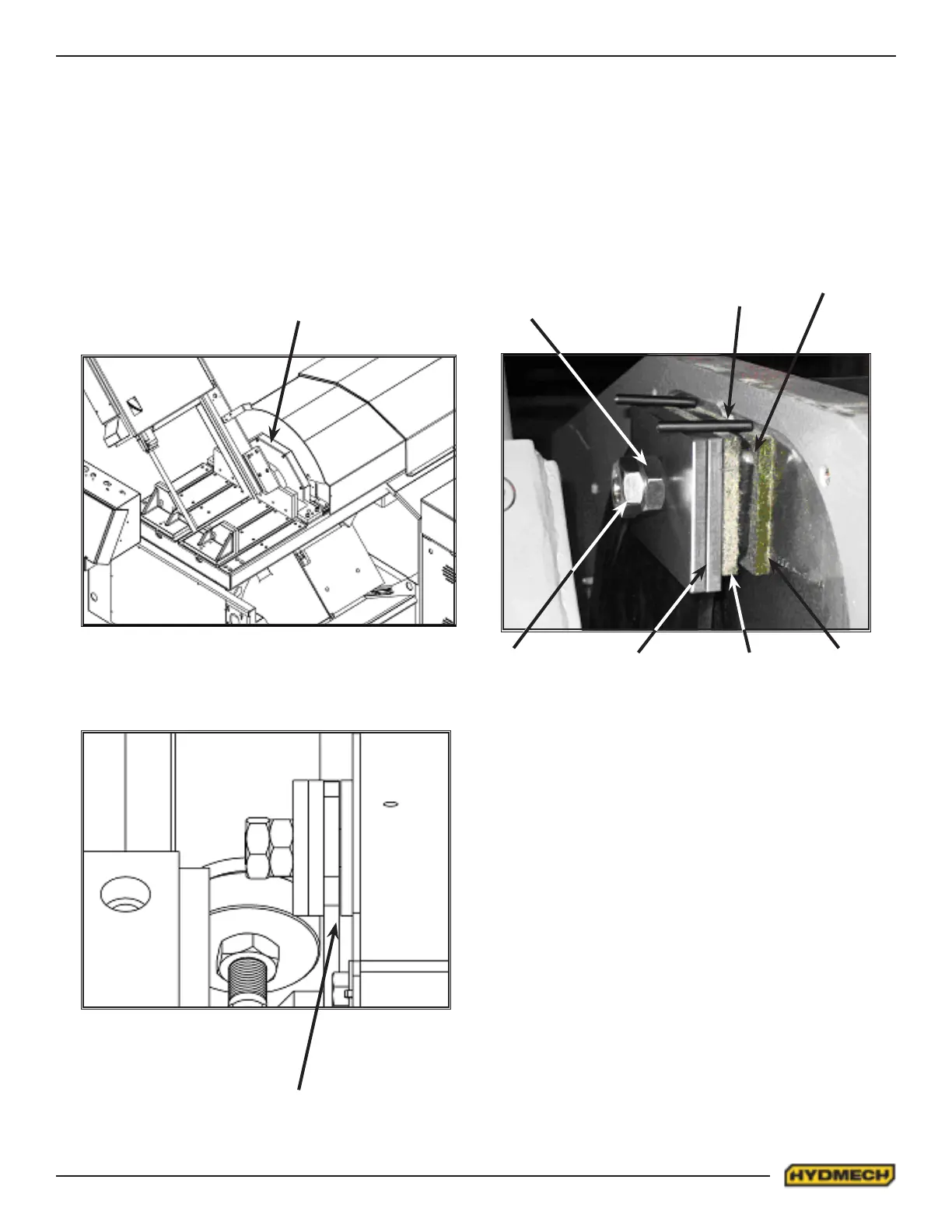
HEAD SWING BRAKE
The brake assembly can be accessed by removing the brake cover. The brake should be adjusted with the head swing
either to the extreme left or right. (Make sure system pressure is set properly). Maintain the machine in swing mode (ei-
ther left or right). THE BRAKE MUST BE FULLY RELEASED. Adjust the brake nut #3 so that the total clearance between
the brake plate #1 and the rear brake pad #5 is .005” - .010”. Lock the jam nut #2. Make sure the two roll pins #7 secure
the brake pads from rotation. Swing the head in both directions through the entire range to make sure the brake is working
properly. Re-install the brake cover.
BRAKE COVER
CLEARANCE .010” MAX
1- Brake plate (V18-272-01)
2- Lock Nut
3- Brake Nut
4- Front Brake Pad (V18-271-01B)
5- Rear Brake Pad (V18-271-01B)
6- Brake Pad Support (V18-271-02A)
7- Roll Pin
Note: Canted head machine takes only 1
Front brake pad support item #6
7
3
2
1
5
46