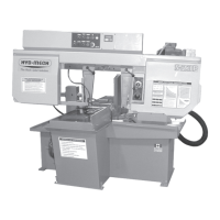
3.5
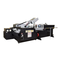
Head forward limit switch
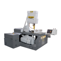
There is one grease nipple for the
idler guide arm slide under the
black plug.
LUBRICATION
The V18 APC was designed with a goal to minimize the maintenance required so
as to reduce downtime. Moving parts of the V18 APC will require periodic lubrica-
tion nonetheless, primarily application of a general purpose grease to the guide
arms, vise ways, and the linear bearings. The following photos show the location
of grease ttings that should be lubricated monthly.
In addition to the grease ttings shown, it is good practice to maintain a constant
greased surface on the vise ways. As the vises are precision t to the vise table,
the constant friction of metal to metal can be eectively alleviated with the appli-
cation of general purpose grease. If the saw is left for long periods without use, an
eective coating of grease will prevent metal to metal adhesion and rust.
GEARBOX LUBRICATION (V18 WITH A412 GEARBOX)
The Bonglioli A412 gearbox used on the V18 is supplied with 5.0 litres (1.32 US gallon) of Mobil SHC 630 synthetic oil.
This oil has an ISO Viscosity Grade of 220 that is optimum for ambient temperatures from 10 – 40 Deg C [70 – 104 Deg
F]. If the machine will be operated for prolonged periods at ambient temperatures below 20 Deg C [70 Deg F] an oil of
ISO Viscosity Grade 150 should be substituted.
The suggested oil change interval is given below:
Oil Temperature
Deg C [Deg F]
Mineral Oil Interval
[hours]
Synthetic Oil Interval
[hours]
< 65 [< 150] 8000 25000
65 – 80 [150 – 175] 4000 15000
80 – 95 [175 – 200] 2000 12500
HEAD FORWARD LIMIT SETTING
The Head Forward Limit is factory set and under normal operating conditions should
not need to be reset.
TO SET LIMIT:
If adjustment of the Shaft Collar is necessary, the Head Forward Limit is an assembly
on the vise cylinder rod. Loosen the set screw that allows setting of the limit switch
actuator, and adjust according to your needs. The photo shows the Head Forward limit
switch assembly. This assembly will be on the same side of the head as the in-feed
conveyor.