MAX200 SETUP
3f-6 CommandTHC for X-Y Table Instruction Manual
7
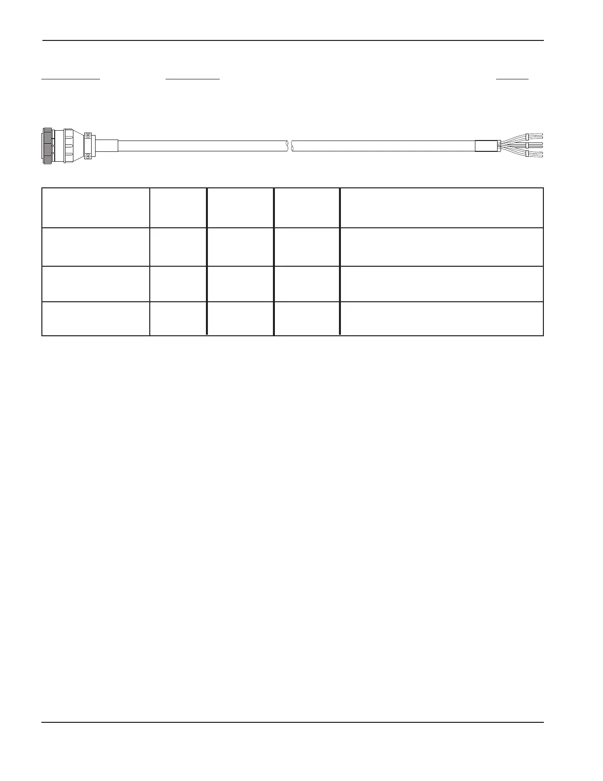
Figure 3f-3 MAX200 interface cable – part number and signal list
Part number
Description Length
123358 MAX200 Power Supply Interface Cable 6 ft./1.8 m
Power Plasma
Supply Interface
Signal Name Color End (1X6) End Function
Hold I/O – Black 5 J4-6 (Optional) Hold Ignition (I/O) signal used for preflow
Hold I/O + White 1 J4-5 during IHS. Also used by power unit to synchronize
Drain Drain 10 operation of multiple torch installations. Output signal.
Plasma Start – Black 9 Relay Plasma Start signal maintained during plasma cut. If
Plasma Start + Green 15 Relay signal is lost, system must be restarted. Output signal.
Drain Drain 14
Arc Transfer (Delayed) – Black 31 J3-2 Arc Transfer signal. Contact closes after arc transfer and
Arc Transfer (Delayed) + Red 36 J3-1 pierce delay (set on power supply front panel).
Drain 25 Dry closure. Input signal.contact
Plasma interface assembly other J3 and J4 connection points:
• J3-5 (+) and J3-6 (–) – Alternate Nozzle Contact. An optically isolated signal that indicates nozzle is in ohmic contact with work.
Ohmic contact is represented by a logic 1.
• J3-7 through J3-12 – Reserved for future use.
• J3-13 and J3-14 – Protective earth ground.
• J4-7 and J4-8 –
Pierce Complete signal used by power unit to time transition from pierce gas flow to cut gas flow. User enters this
time delay into THC. Output signal.
• J4-9 through J4-14 – Reserved for future use.