POWER SUPPLY SETUP
powermax
45
Operator Manual 2-3
Position the power supply
Locate the Powermax45 near an appropriate 200–240 volt power receptacle for CSA or CE
1-phase power supplies, or a 400 volt receptacle for 3-phase CE power supplies. The
Powermax45 has a 10-foot (3 m) power cord. Allow at least 10 inches (0.25 m) of space around
the power supply for proper ventilation.
Prepare the electrical power
The maximum output voltage will vary based on your input voltage and the circuit’s amperage.
Because the current draw varies during startup, slow-blow fuses are recommended as shown in
the chart below. Slow-blow fuses can withstand currents up to 10 times the rated value for short
periods of time.
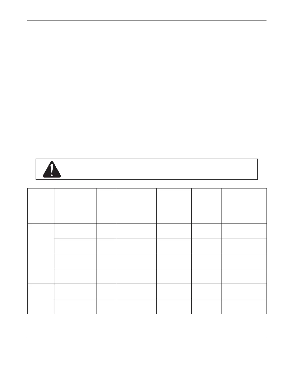
Voltage configurations
The following chart shows the maximum rated output for typical combinations of input voltage and
amperage. Acceptable input voltages can be ±10% of the values given below.
Model Input voltage
Phase
Rated output
Input
current at
6 kw output
Input
current
during arc
stretch
Recommended
slow-blow fuse
size
CSA
200 – 240 VAC 1 45 A, 132 V 34 – 28 A 55 – 45 A 50 A
208 VAC 1 45 A, 132 V 33 A 54.5 A 50 A
CE
200 – 240 VAC 1 45 A, 132 V 34 – 28 A 55 – 45 A 35 or 50* A
400 VAC 3 45 A, 132 V 10 A 15.5 A 15 or 20* A
CE/CCC
220 VAC 1 45 A, 132 V 31 A 53 A 35 or 50* A
380 VAC 3 45 A, 132 V 11 A 14 A 15 A
Caution: Protect the circuit with appropriately sized time-delay
(slow-blow) fuses and a line-disconnect switch.
* Use the higher amperage fuse for applications that require a long arc stretch.