OPERATION
4-2 powermax
45
Operator Manual
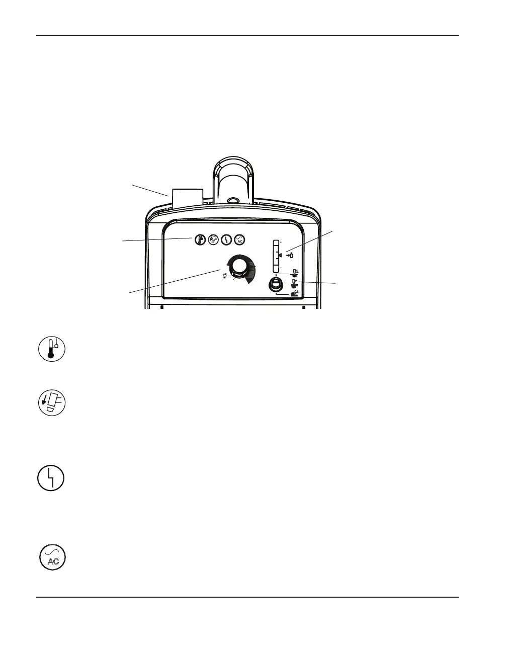
Controls and indicators
The Powermax45 has an ON/OFF switch, an amperage adjustment knob, a pressure regulator knob,
a mode switch, 4indicator LEDs, and a gas pressure LED, which are described below.
40
20
45
AMPS
30
Torch cap sensor LED (yellow)
When illuminated, this LED indicates that the consumables are loose, improperly
installed, or missing. For information on the possible fault conditions, see Basic
troubleshooting in Section 5. If this LED illuminates, the power must be turned OFF, the
consumables installed properly, and the system turned ON again to reset the LED.
Power ON LED (green)
When illuminated, this LED indicates that the power switch has been set to I (ON) and
that the safety interlocks are satisfied.
AC
Front controls and LEDs
Temperature LED (yellow)
When illuminated, this LED indicates that the power supply’s temperature is outside the
acceptable range.
Pressure regulator
knob
Indicator LEDs
Gas pressure LEDs
and pressure bar
Mode switchAmperage
adjustment knob
Fault LED (yellow)
When illuminated, this LED indicates that there is a fault with the power supply. Some
fault conditions will cause one or more of the LEDs to blink. For information on what these
fault conditions are and how to correct them, see Basic troubleshooting in
Section 5.