TORCH SETUP
powermax
45
Operator Manual 3-7
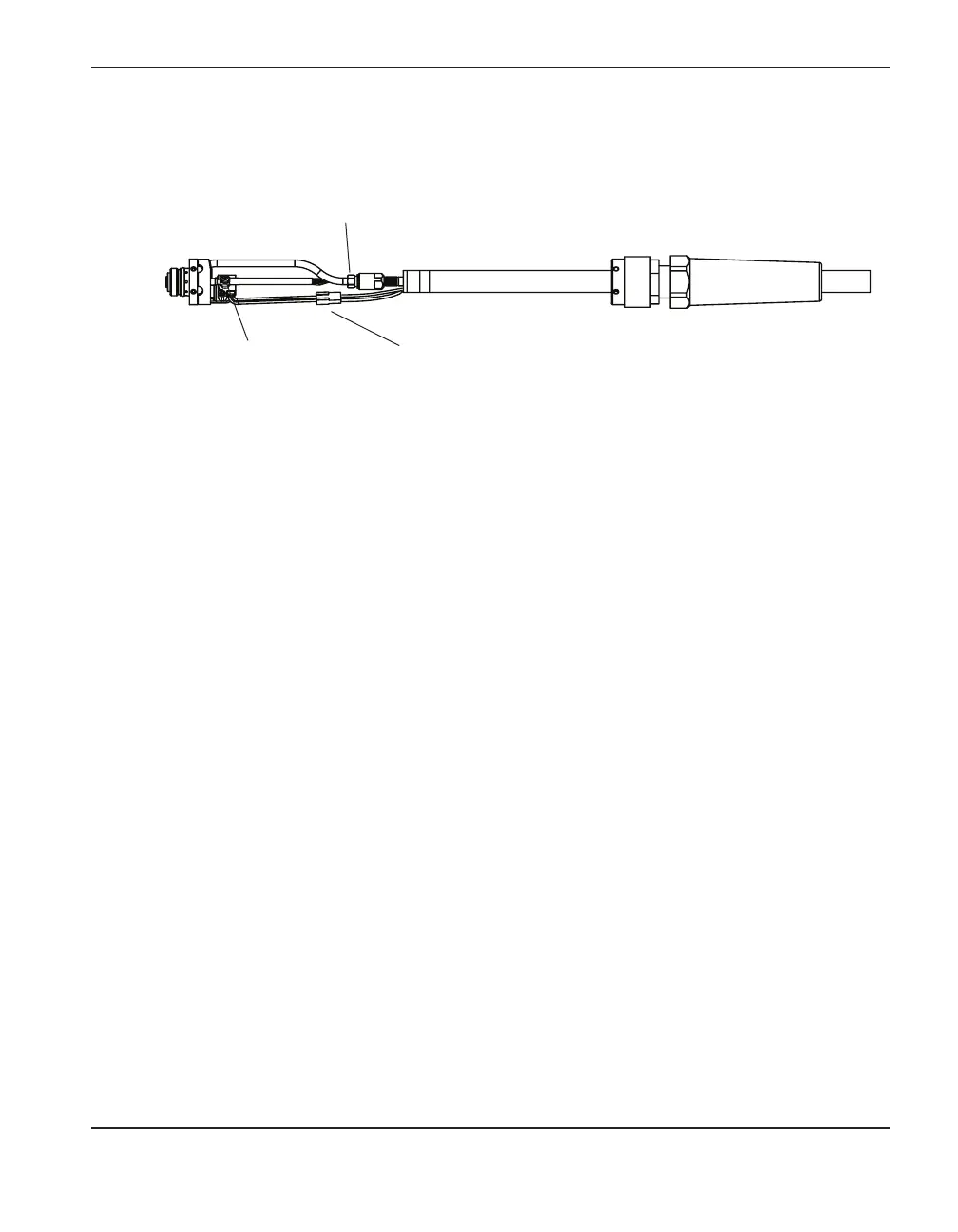
4. Use a #2 Phillips screwdriver and a 1/4-inch nut driver (or adjustable wrench) to remove
the screw and nut that secure the torch’s power cable to the plunger. (Turn the plunger if
necessary to gain access to the screw.)
5. Use 5/16-inch (8 mm) and 3/8-inch (or adjustable) wrenches to loosen the nut that secures
the gas supply line to the torch lead. Set the torch body aside.
Note: Cover the end of the gas line on the torch lead with tape to keep dirt and other
contaminants from getting in the gas line when you route the lead through the track.
6. Route the torch lead through the cutting table’s track.
7. Reattach the torch’s power cable to the torch plunger using the screw and nut. Rotate the
plunger so that the screw does not interfere with the cap-sensor switch.
8. Reconnect the gas line to the torch lead.
9. Press the two halves of the cap-sensor switch’s wire connector together.
10. Slide the positioning sleeve over the torch body and check the alignment of the screw holes.
Replace the three screws at each end.
11. If you will be using the gear rack, re-attach it with the 2 black screws you removed earlier.
12. Attach the torch to the lifter per the manufacturer’s instructions.
Wire connector for
the cap-sensor switch
Gas supply line connection
Screw to connect the
power cable to the plunger
3. Disconnect the wires for the cap-sensor switch at the connector in the middle.