Chapter 4 PLC Features
4.2 Commands
4-18 ME0416-1A
<Caution>
As RX1 is a system domain in CC-Link, turning on the applicable OM would not be reflected to
the host PLC. When the communication with the host PLC is conducted in normal condition, the
values at the RX1 memory assignment on the host PLC side should be on in Bit 11 (0x0B) and
off in other bits. This Bit 11 is a remote READY flag for connection status confirmation.
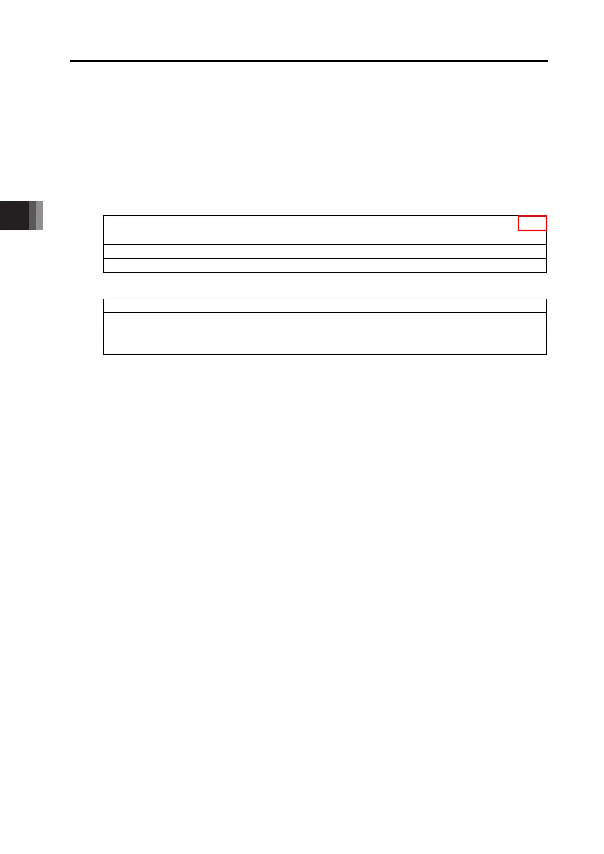
Input and Output Domain Assignment for Fieldbus Communication: Other Networks
FB→LC
Output 0 15 14 13 12 11 10 9 8 7 6 5 4 3 2 1 0
Output 1 31 30 29 28 27 26 25 24 23 22 21 20 19 18 17 16
Output 2 47 46 45 44 43 42 41 40 39 38 37 36 35 34 33 32
Output 3 63 62 61 60 59 58 57 56 55 54 53 52 51 50 49 48
LC→FB
Input 0 79 78 77 76 75 74 73 72 71 70 69 68 67 66 65 64
Input 1 95 94 93 92 91 90 89 88 87 86 85 84 83 82 81 80
Input 2 111 110 109 108 107 106 105 104 103 102 101 100 99 98 97 96
Input 3 127 126 125 124 123 122 121 120 119 118 117 116 115 114 113 112
Described number added to the S1 setting number should be the applicable assignment position
e.g. • When M0 is set to S1, the RXO should be assigned to M0W (from M0 to M15).
• When M512 is set to S1, the output 3 should be assigned to M624W (from M624 to M639).
Assignment should be fixed as shown below.
• CC-Link, CC-Link IE: Input 12 bytes / output 12 bytes
(Setting should be remote device 1 station 1 time for CC-Link)
• Other fieldbus networks: Input 8 bytes / output 8 bytes
 Loading...