Chapter 4 PLC Features
4.2 Commands
4-20 ME0416-1A
The assignment patterns in CC-Link and CC-Link IE Field and the CC-Link station times setting should
be as shown below:
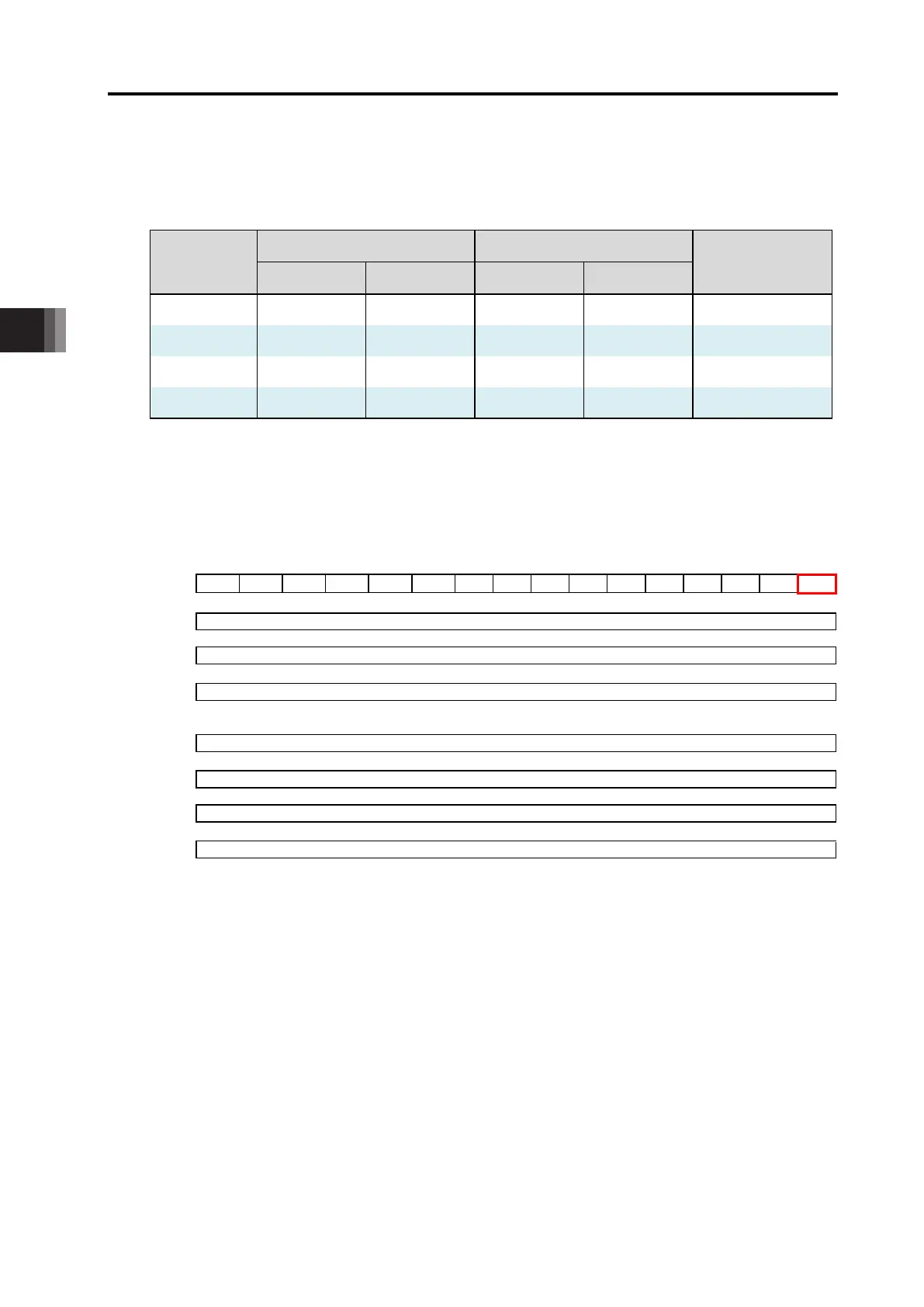
Input and Output Domain Assignment Pattern in CC-Link and CC-Link IE
S2 Setting
Axis Control Signal (Bit) Control Data (Word)
Station Times
Setting
RX RY RWr RWw
1 32 4 1 Station 1 Time
2 64 8 2 Station 1 Time
3 96 12 3 Station 1 Time
4 128 16 4 Station 1 Time
The input and output domain assignment for the fieldbus communication is as shown below.
Input and Output Domain Assignment for Fieldbus Communication: CC-Link, CC-Link IE
FB→LC
RY0 15 14 13 12 11 10 9 8 7 6 5 4 3 2 1 0
~
RYN 16N+15 16N
RWw0 16 (N+1) +15 16 (N+1)
~
LC→FB
48 (N+1) +15 48 (N+1)
~
RXN
RWr0
~
RWr (2N+1)
N = (S2 Setting 2) -1
For CC-Link and CC-Link IE Field, the assignment should be made in the order of RY, RWw, RX
and RWr.
<Caution>
As RXN is a system domain in CC-Link, turning on the applicable OM would not be reflected to
the host PLC. When the communication with the host PLC is conducted in normal condition, the
values at the RXN memory assignment on the host PLC side should be on in Bit 11 (0x0B) and
off in other bits. This Bit 11 is a remote READY flag for connection status confirmation.
 Loading...