Chapter 4 PLC Features
4.2 Commands
ME0416-1A 4-11
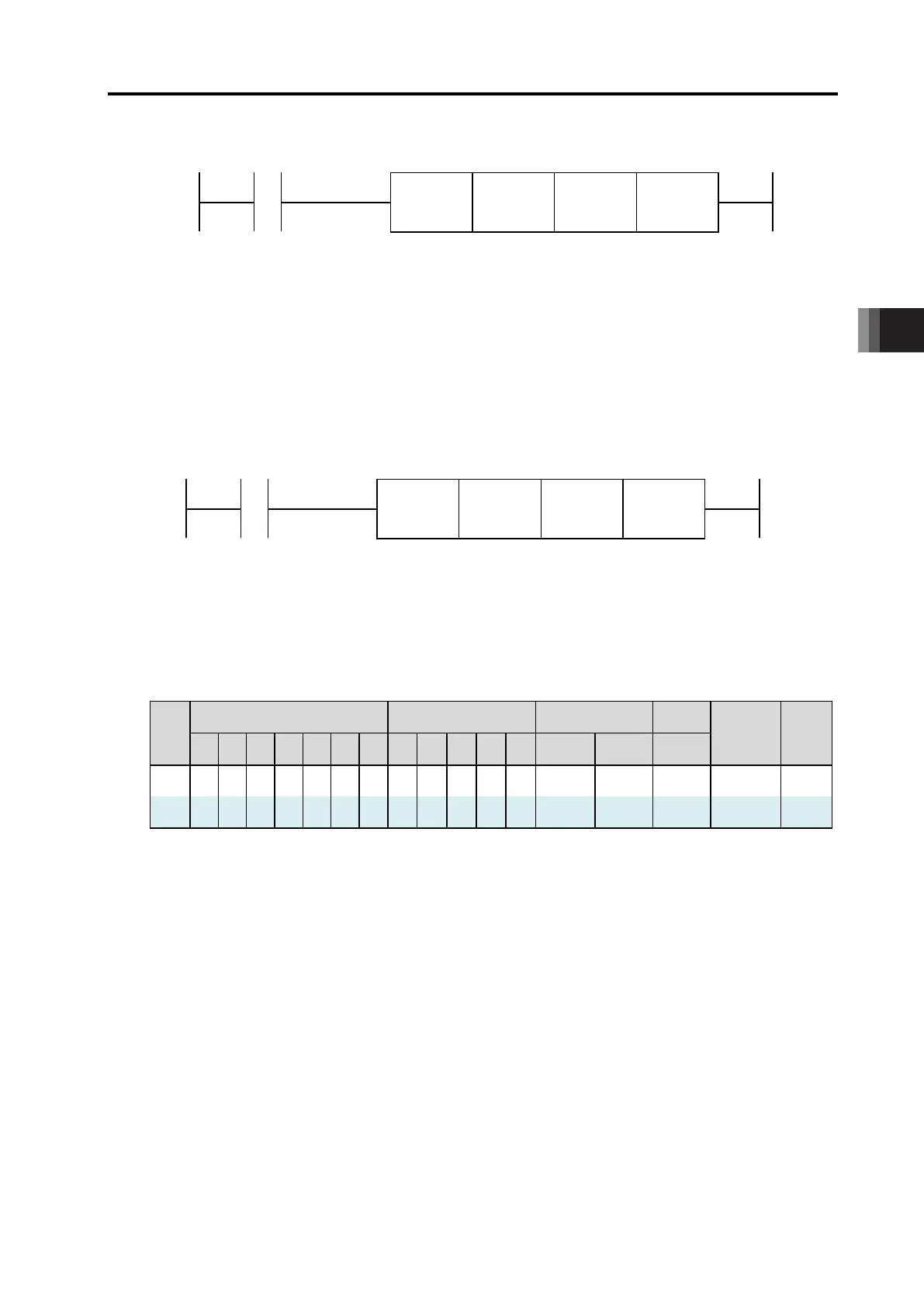
Shown below is how to describe DFC Commands.
DFC
Function
Name
S1 S2
How to Describe DFC Command
[1] Axis Control Command
Axis Control Command assigns the input and output domains controlling the driver unit to the bit
OM domains. By turning on and off the assigned bit OM, it is available to operate the applicable
axes.
Shown below is an example of how to describe the command.
DFC AX0I0E AM0 0
Example of How to Describe Axis Control Command
The range available for use of S1 and S2 is as shown below.
Axis Control Command Available Parameters and Available Range
Bit Word Constant Label
WL
Indication
index
X Y M SM
AM
T C D SD
T C IX DEC HEX L
S1 〇 〇
S2 〇 〇
* It is recommended to have AM set to S1.
With the bit memory set to S1 at the top, the input and output domains to the driver unit should
be assigned. What operation mode to be assigned with should be set in S2.
 Loading...