Chapter 4 PLC Features
4.2 Commands
4-12 ME0416-1A
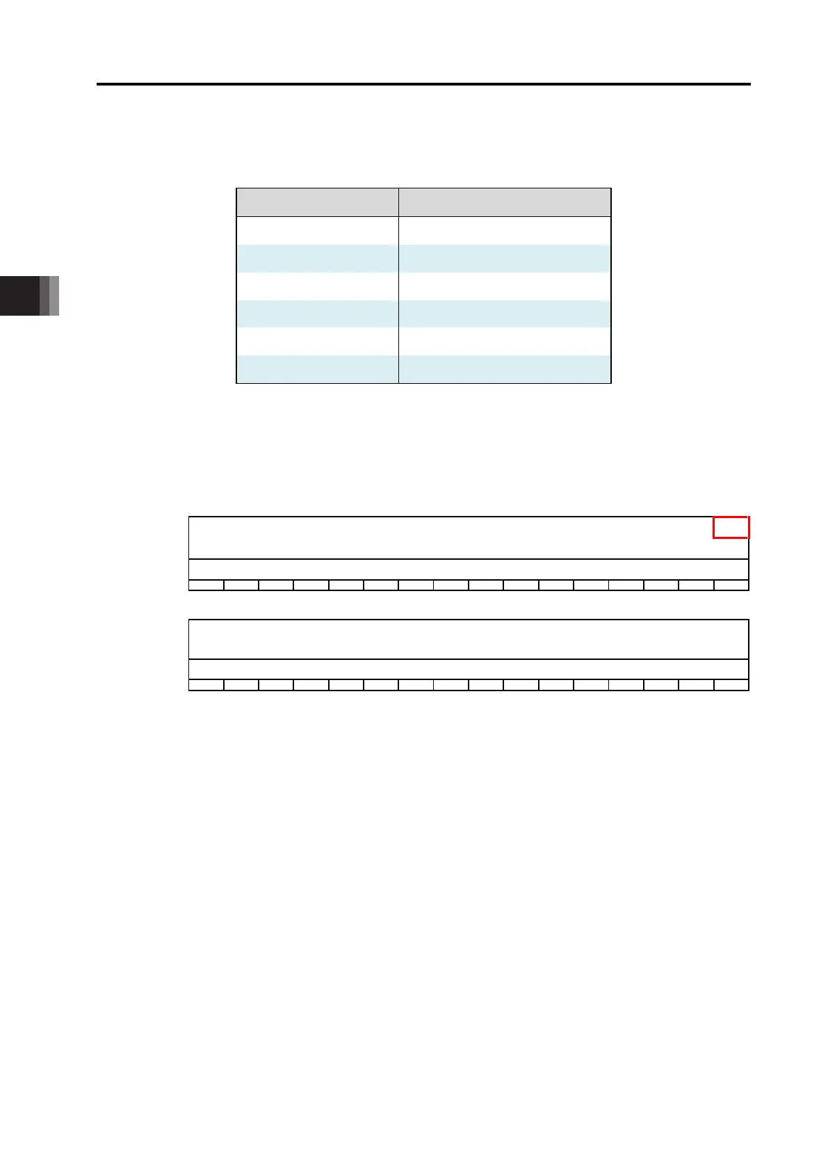
Shown below is the relation between the S2 numbers and the operation modes.
Relation between S2 Setting Number and Operation Mode
S2 Setting Number Operation Mode
0 Simple Direct
1 Positioner 1
2 Positioner 2
3 Positioner 3
4 Direct Numerical Indication
5 Positioner 5
Shown below describes the bit OM domain assignment when set to each operation mode.
The input and output assignment when set to Simple Direct is as shown below.
Input and Output Domain Assignment: Simple Direct
15 14 13 12 11 10 9 8 7 6 5 4 3 2 1 0
31 30 29 28 27 26 25 24 23 22 21 20 19 18 17 16
Completion Position
Number
47 46 45 44 43 42 41 40 39 38 37 36 35 34 33 32
Status Signal Name EMGS CRDY
ZONE2
ZONE1 PZONE
- -
MEND ALML LOAD PSFL SV ALM MOVE HEND PEND
79 78 77 76 75 74 73 72 71 70 69 68 67 66 65 64
95 94 93 92 91 90 89 88 87 86 85 84 83 82 81 80
Indication Position
Number
111 110 109 108 107 106 105 104 103 102 101 100 99 98 97 96
Control Signal Name BKRL
- - - - - -
JOG+ JOG- JVEL JISL SON RES STP HOME CSTR
Described number added to the S1 setting number should be the applicable assignment position.
e.g. • When AM0 is set to S1, the status signal PEND should be assigned to AM48.
• When M256 is set to S1, the completion position number should be assigned to M288W
(from M288 to M303).
 Loading...