Chapter 4 PLC Features
4.2 Commands
ME0416-1A 4-13
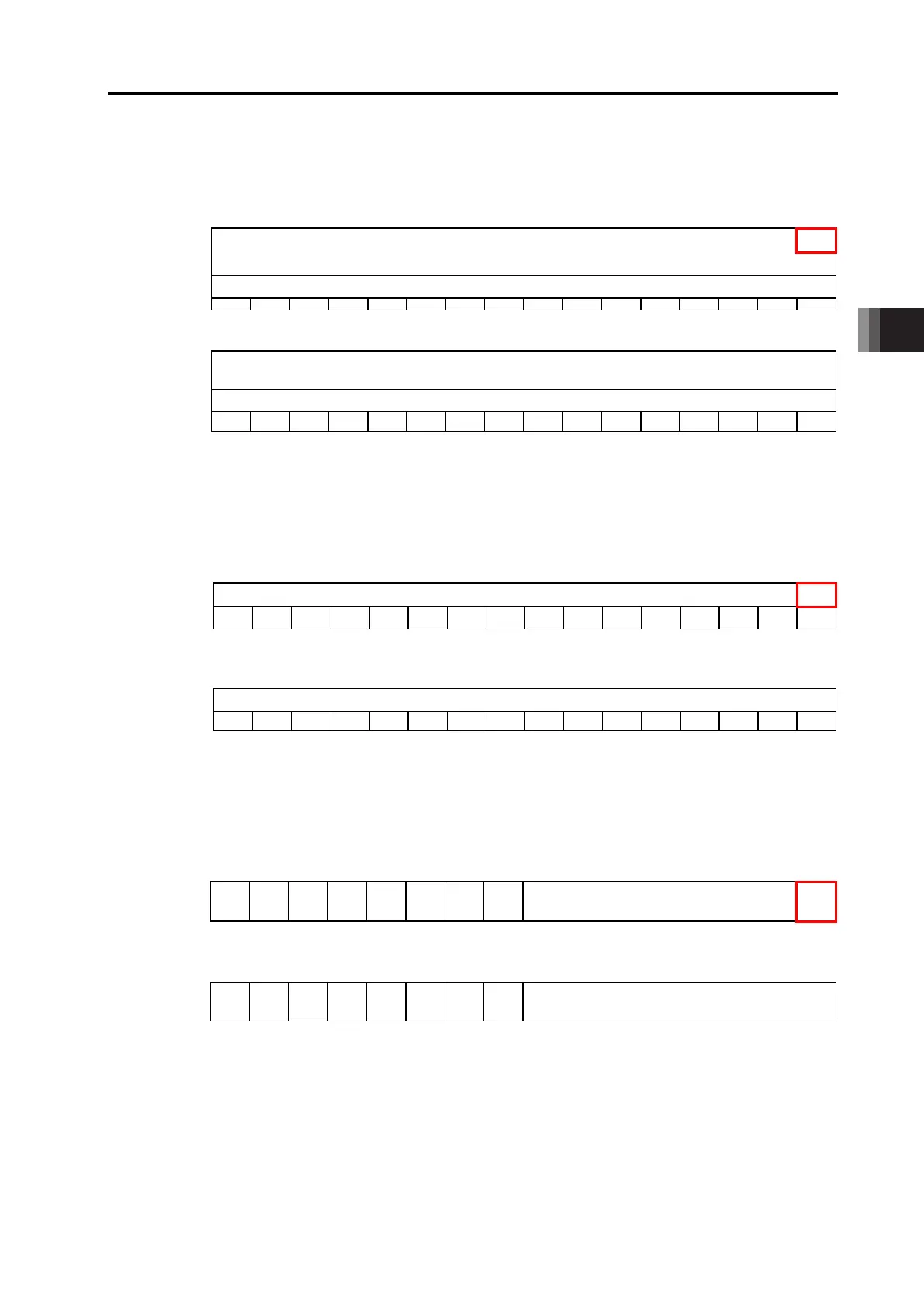
The input and output assignment when set to Positioned 1 is as shown below.
Input and Output Domain Assignment: Positioner 1
Drv→LC
15 14 13 12 11 10 9 8 7 6 5 4 3 2 1 0
31 30 29 28 27 26 25 24 23 22 21 20 19 18 17 16
Completion Position
Number
47 46 45 44 43 42 41 40 39 38 37 36 35 34 33 32
LC→Drv
95 94 93 92 91 90 89 88 87 86 85 84 83 82 81 80
Indication Position
Number
111 110 109 108 107 106 105 104 103 102 101 100 99 98 97 96
Control Signal
Control Signal Name BKRL
- - - -
MODE PWRT JOG+ JOG- JVEL JISL SON RES STP HOME CSTR
The input and output assignment when set to Positioned 2 is as shown below.
Input and Output Domain Assignment: Positioner 2
Drv→LC
Completion Position
Number
15 14 13 12 11 10 9 8 7 6 5 4 3 2 1 0
Status Signal 31 30 29 28 27 26 25 24 23 22 21 20 19 18 17 16
Status Signal Name EMGS CRDY ZONE2 ZONE1 PZONE
MODES
WEND MEND ALML LOAD PSFL SV ALM MOVE HEND PEND
LC→Drv
Indication Position
Number
47 46 45 44 43 42 41 40 39 38 37 36 35 34 33 32
Control Signal 63 62 61 60 59 58 57 56 55 54 53 52 51 50 49 48
Control Signal Name BKRL
- - - -
MODE PWRT JOG+ JOG- JVEL JISL SON RES STP HOME CSTR
The input and output assignment when set to Positioned 3 is as shown below.
Input and Output Domain Assignment: Positioner 3
Drv→LC
Completion Position
15 14 13 12 11 10 9 8 7 6 5 4 3 2 1 0
Status Signal Name EMGS ZONE1 PSFL SV ALM MOVE HEND PEND
-
PM64 PM32 PM16 PM8 PM4 PM2 PM1
LC→Drv
Indication Position
31 30 29 28 27 26 25 24 23 22 21 20 19 18 17 16
Control Signal Name BKRL
- -
SON RES STP HOME CSTR
-
PC64 PC32 PC16 PC8 PC4 PC2 PC1
 Loading...