Form factor
The FC 5273 and FC EL2N are short, low-prole adapters; the FC 5735 and FC EL58 are short, full-
height adapters.
FC compatibility
2, 4, 8 Gigabit.
Cables
Cables are the responsibility of the customer.
Use multimode ber optic cables with shortwave lasers that adhere to the following specications:
• OM3: Multimode 50/125 micron ber, 2000 MHz x km bandwidth
• OM2: Multimode 50/125 micron ber, 500 MHz x km bandwidth
• OM1: Multimode 62.5/125 micron ber, 200 MHz x km bandwidth
Because core sizes are different, OM1 cables can only be connected to other OM1 cables. For best
results, OM2 cables should not be connected to OM3 cables. However, if an OM2 cable is connected
to an OM3 cable, the characteristics of the OM2 cable apply to the entire length of the cables. The
following table shows the supported distances for the different ber optic cable types at different link
speeds.
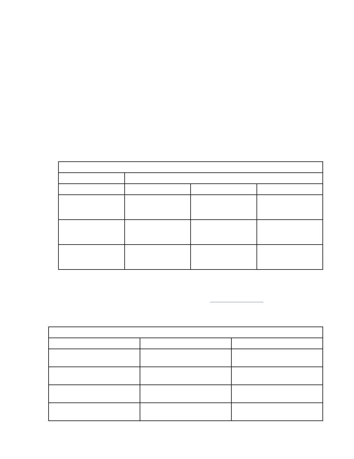
Table 13. Supported distances for multimode ber optic cables
Header Cable Type and Distance
Rate OM1 OM2 OM3
2.125 Gbps 0.5 meters to 150
meters (1.64 feet to
492.12 feet)
0.5 meters to 300
meters (1.64 feet to
984.25 feet)
0.5 meters to 500
meters (1.64 feet to
1640.41 feet)
4.25 Gbps 0.5 meters to 70
meters (1.64 feet to
229.65 feet)
0.5 meters to 150
meters (1.64 feet to
492.12 feet)
0.5 meters to 380
meters (1.64 feet to
1246.71 feet)
8.5 Gbps 0.5 meters to 21
meters (1.64 feet to
68.89 feet)
0.5 meters to 50
meters (1.64 feet to
164.04 feet)
0.5 meters to 150
meters (1.64 feet to
492.12 feet)
Adapter LED
Green and yellow LEDs can be seen through openings in the mounting bracket of the adapter. Green
indicates rmware operation and yellow signies port activity. Table 14 on page 62 summarizes the link
rate conditions. There is a 1-second pause when the LED is off between each group of fast flashes (2, 3,
or 4). Observe the LED sequence for several seconds to be sure that you have correctly identied the
state.
Table 14. Normal LED states
Green LED Yellow LED State
Slow flash Off Normal, link inactive or not
started
On 2 fast flashes 2 Gbps link rate - normal, link
active
On 3 fast flashes 4 Gbps link rate - normal, link
active
On 4 fast flashes 8 Gbps link rate - normal, link
active
62 Power Systems: Managing PCIe adapters