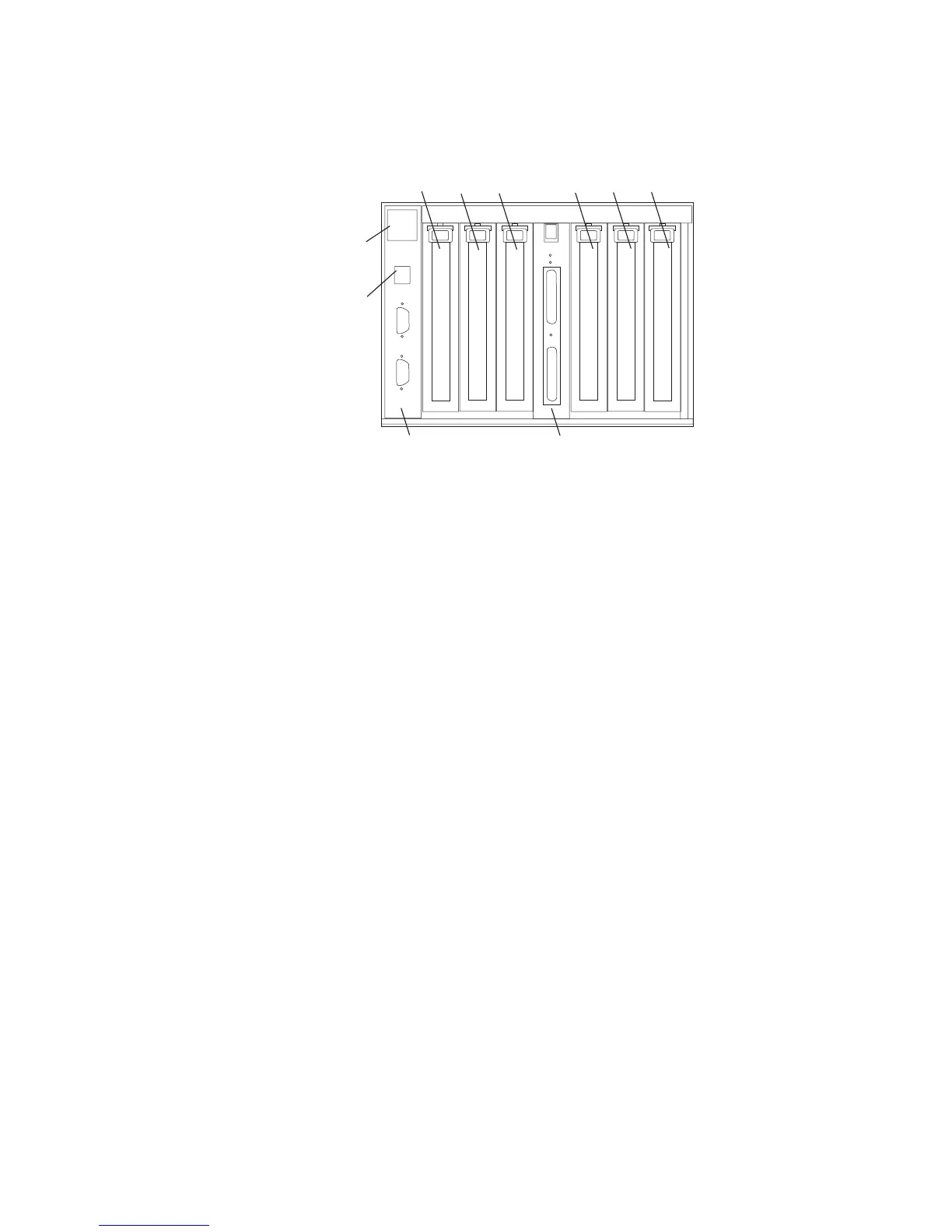
The following figure shows the I/O subsystem from the rear.
1
23 456
1
23
4
56
78
9
10
1 PCI adapter slot 1 6 PCI-X adapter slot 6
2 PCI-X adapter slot 2 7 RIO bus adapter card
Upper connector 0
Lower connector 1
3 PCI-X adapter slot 3 8 SPCN connector card
Upper connector J15
Lower connector J16
4 PCI-X adapter slot 4 9 Rack beacon connector
5 PCI-X adapter slot 5 10 Power cord channel
D10 Operator Indicators
v LED indicators visible on each PCI adapter cassette
v LED indicators on the I/O subsystem backplane
v Attention/Identify LEDs for power supplies and fans
D10 PCI-X Slots
The Model D10 has six PCI adapter slots. Five PCI-X slots and one PCI slot. Adapters
are installed and removed using a PCI adapter cassette which allows adapters to be
installed without turning off the power or opening the I/O subsystem covers.
The slots are numbered on the rear of the chassis from left to right 1 through 6. PCI
adapters are installed using an adapter cassette. The adapter cassette shows two LEDs
for each adapter. There is a green power indicator LED (upper) and an amber
fault/identify LED (lower). Slot 1 is a 5V PCI slot. Slots 2 through 6 are 3.3V PCI-X.
2 Eserver pSeries 7311 Model D10 and Model D20 Service Guide