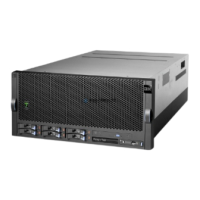
Do you have a question about the IBM pSeries 630 6C4 and is the answer not in the manual?
Provides a logical description and a physical overview of the system.
Details the bus architecture, PCI-X slots, processors, memory, media bays, and power supplies.
Describes the available processor types and speeds, and configuration options.
Details memory configurations, including ECC DDR SDRAM and DIMM slot population.
Lists available media drives like CD-ROM, DVD-ROM, diskette, and tape drives.
Details the four hot-pluggable disk-drive bays and available disk-drive sizes and speeds.
Explains expansion options using additional 7311 Model D20 I/O drawers for PCI-X slots and disk drive bays.
Describes the system's power supplies, including AC input types and redundant power capabilities.
Details the operator panel components including the LED diagnostics display and buttons.
Explains physical location codes and AIX location codes for mapping failing FRUs.
Provides a table mapping component names to their physical and AIX location codes.
Illustrates system cable connections and internal power cable routing.
Contains system specifications for both Model 6C4 and Model 6E4, including dimensions, electrical, and environmental data.
Provides a checklist for performing a service inspection on the system.
Guides the trained service representative through the system for isolation and error recovery.
Explains the system attention LED on the operator panel and its indication of needed user intervention or service.
Describes checkpoints, error codes, and SRNs that appear during service processor boot and system operation.
Provides guidance on isolating failing components using error codes and referencing relevant sections for actions.
Details the Service Focal Point application for diagnosing and repairing problems on partitioned systems.
Explains how to access system logs for error information depending on system configuration (HMC attached or not).
Provides procedures to reset the system attention LED based on system configuration (HMC attached or not).
The starting point for problem determination, quickly pointing to appropriate MAPs or service reference information.
A subset of the Entry MAP that helps to save time for some types of problems.
Provides a structured analysis method to get an error code and lists service processor settings.
Used to locate problems in the processor subsystem, I/O subsystem, or rack.
Describes the system's LEDs that help identify various components and locate failing FRUs.
Troubleshoots power failures in the base system drawer when no error codes are available.
Troubleshoots situations where the I/O drawer does not power on and the Power Present LED is off.
Addresses a base system power supply load fault indicated by SPCN error codes.
Guides troubleshooting for problems indicated by JTAG error codes.
Used to locate defective FRUs not found by normal diagnostics in I/O subsystems.
Used to locate defective FRUs not found by normal diagnostics in the processor subsystem.
Explains the Initial Program Load (IPL) process when an HMC is attached to the system.
Explains the Initial Program Load (IPL) process when no HMC is attached to the system.
Lists and describes checkpoints that appear on the operator panel or virtual terminal during boot.
Provides a list of service processor checkpoints and their corresponding actions or possible failing FRUs.
Details firmware checkpoints in the Exxx to EFFF range useful for diagnosing problems.
Provides steps to perform a slow-mode boot for thorough analysis of available information before hardware repair.
Guides on finding the error code that originally sent you to the Checkpoint and Error Code Index.
Lists four-character progress codes and checkpoints found in Firmware Checkpoints.
Explains how to find the location code for error codes where it is not explicitly provided.
Lists SPCN error codes for the CEC and their corresponding actions or possible failing FRUs.
Lists firmware error codes and their associated actions or possible failing FRUs.
Provides a comprehensive list of Service Processor error codes and their corresponding actions.
Provides considerations for using diagnostics, including error log access and partition resources.
Explains how to identify the terminal type when running diagnostics.
Describes the modes for running online diagnostics: Service, Concurrent, and Maintenance.
Provides steps to run online diagnostics in service mode when an HMC is attached.
Provides steps to run online diagnostics in service mode when no HMC is attached.
Guides on running standalone diagnostics from a NIM server.
Details the groups of service processor menus: General User and Privileged User.
Explains how to access service processor menus using an ASCII terminal or HMC virtual terminal.
Provides access to setup options like passwords, console mirroring, and OS surveillance.
Allows setting power control options, including unattended start, reboot policy, and system boot modes.
Provides information and instructions for updating system firmware.
Explains how to check the current firmware level of the system.
Allows changing the language used by the System Management Services menus.
Enables selecting from password utilities like setting or removing privileged-access passwords.
Allows viewing or clearing the system's error log.
Enables and sets up the remote startup capability of the system or partition.
Allows selecting which console to use for displaying SMS menus.
Provides options to view and set installation and boot device configurations.
Provides precautions for handling static-sensitive devices like electronic boards and drives.
Details how to shut down the system and its applications before installing options.
Explains how to power off a system with HMC attached and AIX installed.
Provides steps for powering on the system after all necessary connections are made.
Describes how to power on the system using the HMC interface after cable installation.
Covers the removal and replacement of the system's drawer-release latch and brackets.
Details the procedure for placing the Model 6C4 into the service position for maintenance.
Procedures for removing and replacing system covers like access covers and bezels.
Provides information on installing, removing, and managing PCI adapters.
Details the procedure for removing a hot-pluggable PCI adapter.
Provides steps to install a new PCI hot-plug-capable adapter into the system.
Covers procedures for removing and replacing processor and PCI adapter cooling fans.
Details procedures for removing and replacing media drives like CD-ROM, diskette, and tape.
Provides procedures for deconfiguring, removing, and replacing hot-plug disk drives.
Covers the removal and replacement of PCI riser cards.
Details procedures for removing and replacing the disk drive backplane.
Covers the removal and replacement of the operator panel assembly.
Explains how to update the system VPD information after replacing the operator panel.
Covers the removal and replacement of processor cards.
Provides procedures for removing and replacing memory DIMMs.
Details the procedure for replacing the system's battery.
Covers procedures for removing and replacing power supplies.
Provides steps to remove a non-hot-swap power supply.
Provides steps to replace a non-hot-swap power supply.
Details the procedure for removing a hot-swap power supply.
Provides steps to replace a hot-swap power supply.
Details the procedure for replacing the CEC backplane (system board).
Contains a list of system parts with FRU part numbers, units per assembly, and descriptions.
Explains the encoding of the 'x' in SRNs, related to FRU replacement, hot swap, and software/firmware issues.
Lists Service Request Numbers (SRNs) with descriptions and corresponding actions for Linux systems.
Describes the operator panel display components and their functions.
Identifies system component LEDs (green and amber) and their status indications.
Provides a checklist for setting up and testing the service processor, including modem configuration.
Contains sample testing procedures for call-in and call-out functions.
Guides on configuring serial ports on an AIX system.
Contains specifications for the 7014 Model T00 and T42 rack, including dimensions and electrical data.
Defines terms related to noise emission levels for machines.
Illustrates the minimum space required for units during service, including rack configuration.
Details the procedure for installing rack-mounting hardware and system rails.
Provides procedures for removing the system drawer from the rack.
Guides on installing the Model 6C4 onto a Type 1 system rail assembly.
Guides on installing the Model 6C4 onto a Type 2 system rail assembly.
Details connecting the RIO-2 cable support bracket to the back of the Model 6C4 chassis.
Covers the installation of the Model 6C4 cable-management arm.
Provides guidance on positioning the HMC and monitor for safe and comfortable setup.
Explains how to connect the monitor, mouse, and keyboard to the HMC.
Recommends connecting the LAN cable for active partition error reporting to the HMC.
Details how to plug in the HMC power cable.
Guides on configuring network settings like IP address, Name Services, and Routing.
Explains how to set up Inventory Scout Services for managed systems and partitions.
Describes collecting Vital Product Data (VPD) for the managed system into a file.
Provides steps to configure the Service Agent, including network settings and registration.
Provides sample modem configuration files for various modems.
Explains how to create or modify modem configuration files using the Configure Remote Maintenance Policy Service Aid.
Guides on selecting the appropriate modem configuration file based on modem type and features.
| Model | IBM pSeries 630 6C4 |
|---|---|
| Category | Server |
| Processor | POWER4 |
| Processor Speed | 1.2 GHz |
| Number of Processors | 1 or 2 |
| L2 Cache | 1.5 MB per processor |
| L3 Cache | 32 MB |
| Network | 10/100/1000 Mbps Ethernet |
| Operating System | AIX |
| Architecture | 64-bit |
| Memory Type | SDRAM |
| Hard Drive | 36.4 GB, 73.4 GB |
| Storage Interface | SCSI |
| Form Factor | Rack-mounted |


