Drawer-Release Latch Bracket Replacement
To replace the Model 6C4 drawer-release latch brackets, do the following:
1. If you have not already done so, open the front rack door and place the system into the service
position as described in “Placing the Model 6C4 into the Service Position”.
2. Using the supplied retaining screws, secure the latch brackets to the side of the Model 6C4.
Note: The latch brackets are right-side and left-side dependent.
3. Replace the release latch as described in “Drawer-Release Latch Replacement” on page 428.
4. Replace the front bezel as described in “Front Bezel Replacement (Model 6C4)” on page 442.
5. Push the system drawer back into the operating position as described in “Returning the Model 6C4 to
the Operating Position” on page 430.
Placing the Model 6C4 into the Service Position
Attention: When placing the Model 6C4 into the service position, it is essential that all stability plates
must be firmly in position to prevent the rack from toppling. Ensure that only one system drawer at a time
is in the service position.
Before doing any service actions inside the Model 6C4, you must put the system into the service position.
To place the system into the service position, do the following:
1. Open the front rack door.
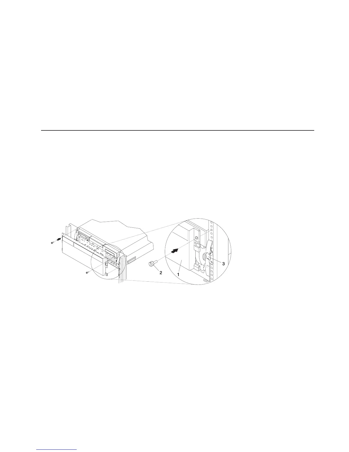
2. If your system is equipped with two thumbscrews securing it to the rack, remove the thumbscrews. The
screws are located on the bezel, just above each system-release latch.
1 Model 6C4 Front Bezel
2 M5 16-mm Retaining Screw
3. Release the system-release latches on both the left and right sides.
4. Pull the system drawer out from the rack until the rails are fully extended.
Note: When the system rails are fully extended, safety latches on the slide rails lock into place. This
action prevents the system from being accidentally pulled out too far and dropped. The following
illustration shows a system drawer in the service position.
Chapter 9. Removal and Replacement Procedures 429
 Loading...


