System Internal Cables
The following diagrams show the system cable connections. The following diagram illustrates the routing of
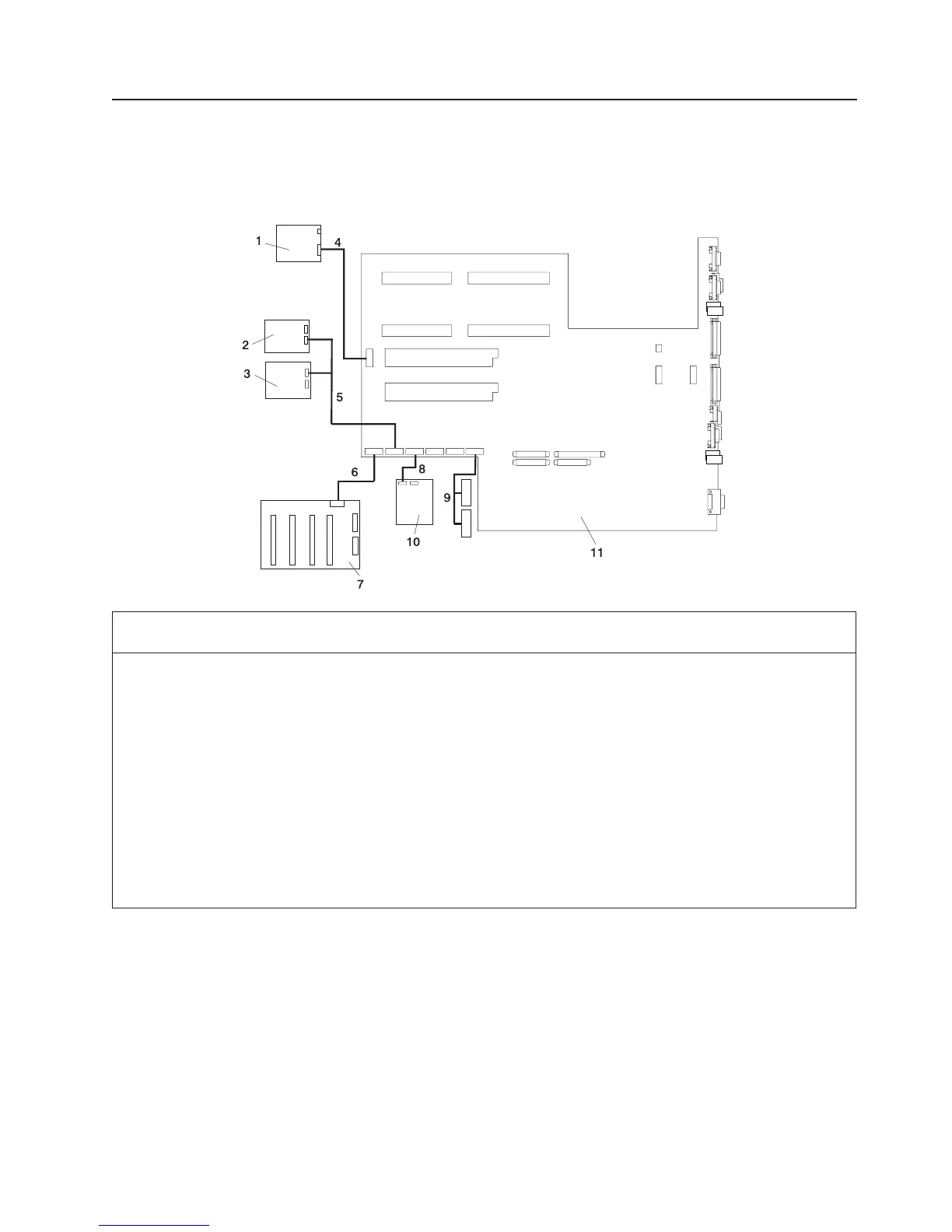
the internal power cables.
Internal Power Cable Routing Diagram
Index Number FRU Part
Number
Units Per
Assembly
Description
1 00P3210 1 Operator Panel
2 See Note 1 IDE CD-ROM
3 See Note Up to 2 SCSI Media Device
4 09P5870 1 CEC Backplane to Operator Panel Signal / Power Cable
5 09P5867 1 2-drop Power Cable from CEC Backplane to IDE
CD-ROM and other SCSI Media Devices
6 09P5888 1 CEC Backplane to Disk Drive Backplane Power Cable
7 00P4132 1 Disk Drive Backplane
8 09P5864 1 Diskette Drive to CEC Backplane Power Cable
9 09P5900 1 PCI Cooling Fans #3 and #4 Power Cable
10 See Note 1 Diskette Drive
11
00P4488 1
CEC Backplane
00P5830 1
Notes:
1. For more information on power cables, go to “External AC Power Cables” on page 47.
2. See RS/6000 Eserver pSeries Diagnostic Information for Multiple Bus Systems for part numbers.
Internal Signal Cable Routing Diagram
The following diagram illustrates the routing of the signal cables.
Chapter 10. Parts Information 523
 Loading...


