System Cables
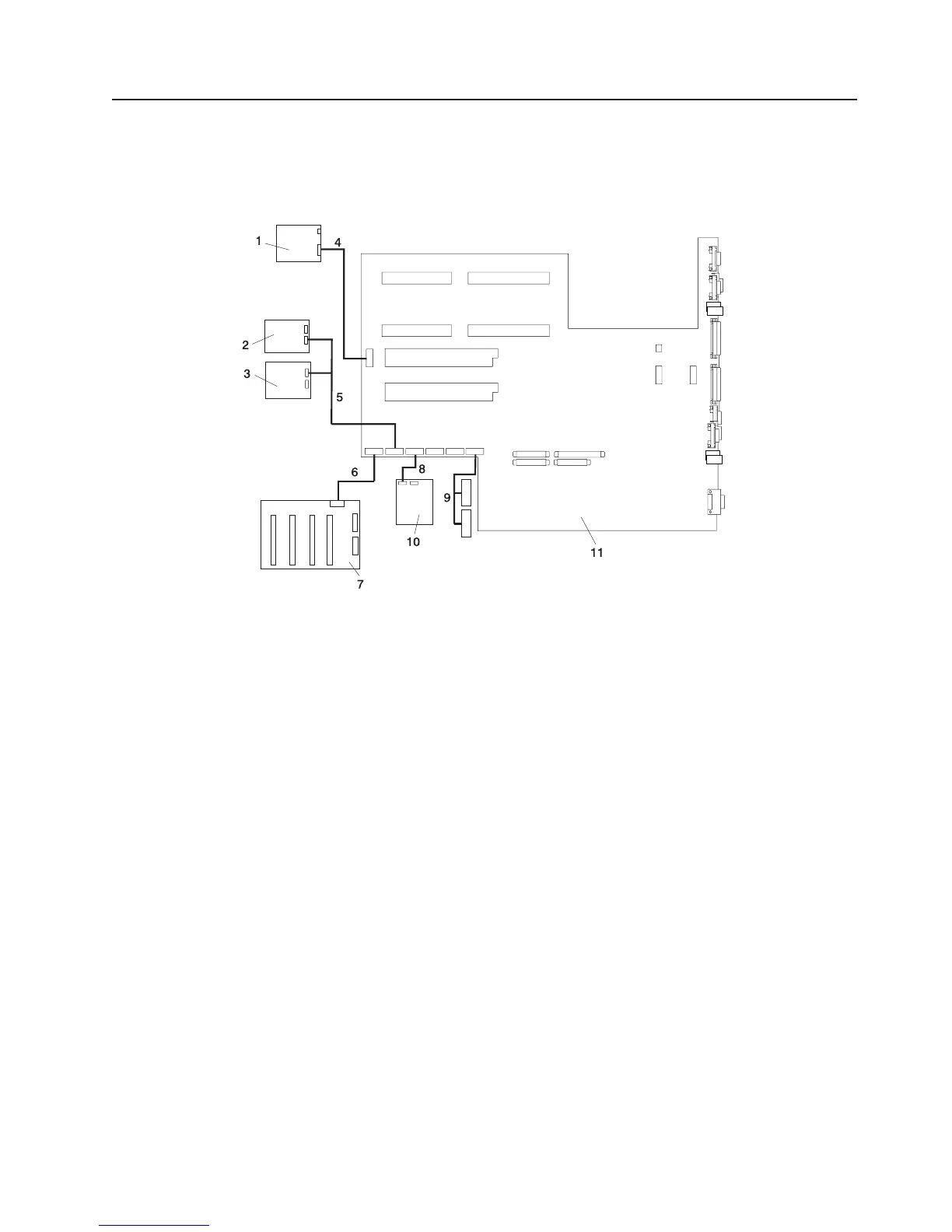
The following diagrams show the system cable connections. The following diagram illustrates the routing of
the internal power cables.
Internal Power Cable Routing Diagram
1 Operator Panel
2 IDE CD-ROM
3 SCSI Media Device
4 CEC Backplane to Operator Panel Signal/Power Cable
5 2-drop Power Cable from CEC Backplane to IDE CD-ROM and other SCSI Media Devices
6 CEC Backplane to Disk Drive Backplane Power Cable
7 Disk Drive Backplane
8 Diskette Drive to CEC Backplane Power Cable
9 PCI Cooling Fans #3 and #4 Power Cable
10 Diskette Drive
11 CEC Backplane
Chapter 1. Reference Information 39
 Loading...


