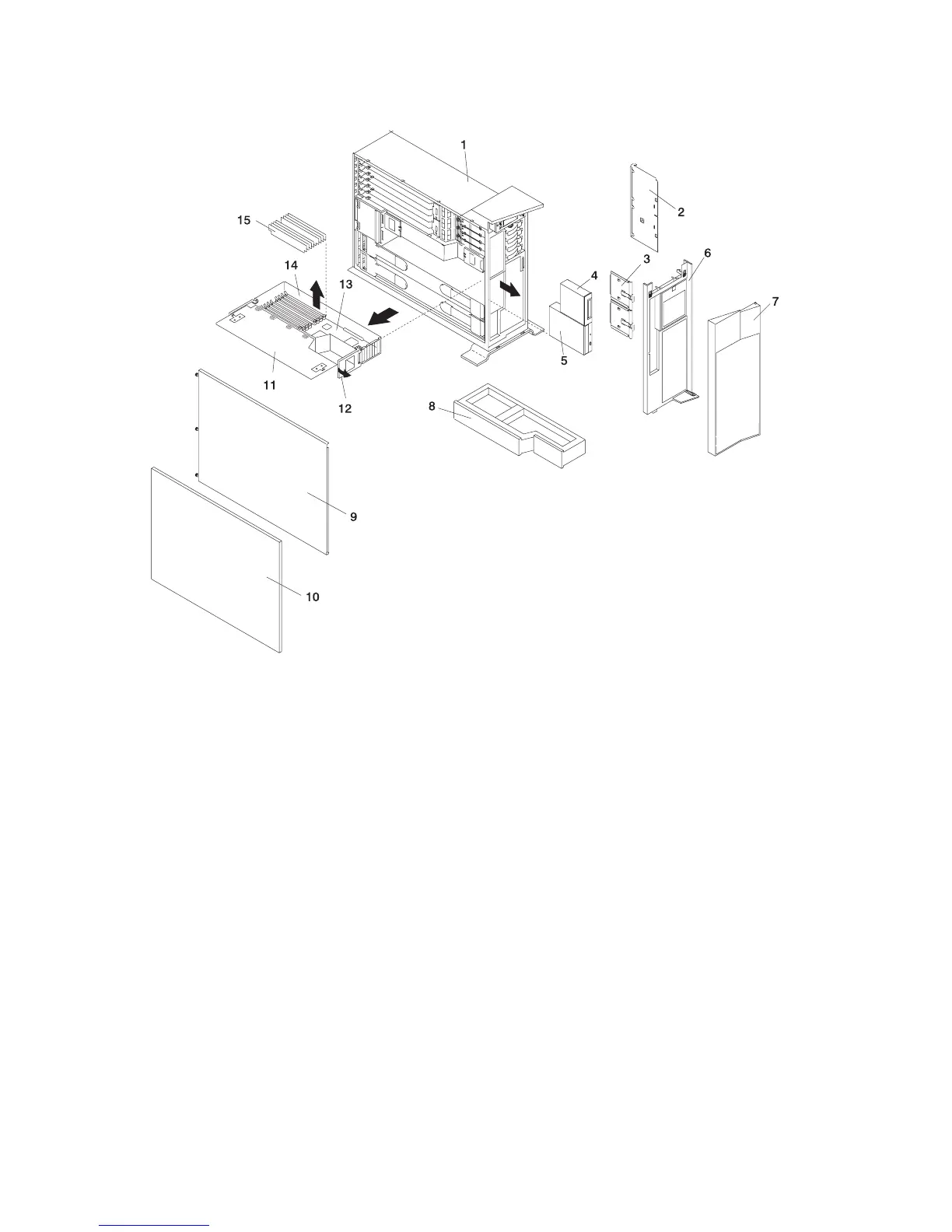
Model 6E4 Processor Card
1 Model 6E4 9 Service Access Cover
2 Media Device Support Shelf 10 Outer Side Cover
3 Media Carrier Trays 11 Processor Access Cover
4 Optional Media Device (for example:
Diskette Drive or Tape Drive)
12 Processor Assembly Lifting and
Release Handles
5 IDE CD-ROM Drive 13 Processor Card
6 Front Bezel 14 Processor Assembly
7 Bezel Door 15 Memory DIMMs
8 Processor Filler
Adding or Replacing a Processor Card
Notes:
1. Adding an additional processor card or installing a new processor card into your system may require
the updating of the system firmware.
2. Before handling any card, board, or memory DIMM, touch any metal surface of the chassis with one
hand to minimize static electricity discharge. Refer to “Handling Static-Sensitive Devices” on page 423.
3. If your system is configured with one processor card, place the card into location U0.1-P1-C1 on the
CEC backplane. The remaining processor connector must have the processor filler panel in place. The
filler panel protects the connector located on the CEC backplane from dust or damage and assists in
airflow and cooling.
490 Eserver pSeries 630 Model 6C4 and Model 6E4 Service Guide
 Loading...


