7. Finger-tighten a second retaining screw through the top screw hole of the latch bracket. After the
latch bracket is in place, ensure that both screws are finger-tight.
Attention: Do not tighten any of the screws more than finger-tight until instructed to do so.
Tightening the screws prevents the rails from self-aligning when the system drawer is attached.
8. Go to the rear of the rack.
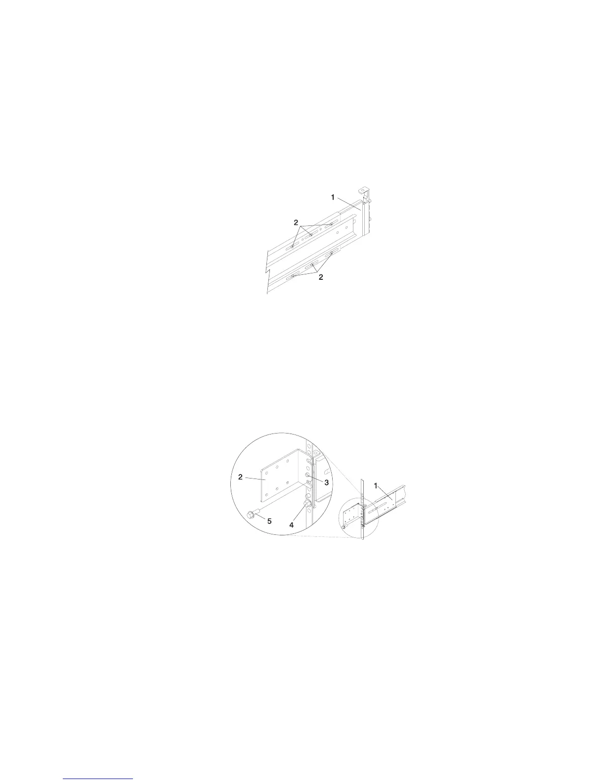
9. Loosen, but do not remove, the six retaining screws that secure the rail-length adjusting plate to the
rail.
Note: The rail-length adjusting plate should not move freely when loosened.
1 Rail-Length Adjusting Plate
2 Retaining Screws for Rail-Length Adjusting Plate
10. Facing the rear of the rack, ensure that the right rail’s two alignment pins are positioned in the correct
EIA unit’s holes. Use two rack-retaining screws to attach the rail brackets to the rack flanges.
Finger-tighten both screws.
11. Using a screwdriver, tighten the six screws that secure the rail-length adjusting plate.
12. Locate the bracket that attaches the cable management arm to the rack flange.
13. Repeat substeps 1 through 11 when installing the left rail.
1 Rail Assembly (Labeled ″Left″ in the Front Lower Corner)
2 Rack to Cable Management Arm Bracket
3 Top Rear Alignment Pin
4 Bottom Screw
5 Top Screw
14. Position the bracket’s bottom hole over the rail’s top alignment pin.
Note: The bracket’s bottom slot should now align with the top screw hole of the rail flange.
Appendix D. Setting Up the System 577
 Loading...


