11. From the bottom of the processor assembly, lift the side access cover. Four hinges hold the cover to
the top of the processor assembly. Pivot the cover up to reveal the memory DIMMs or DIMM
connectors.
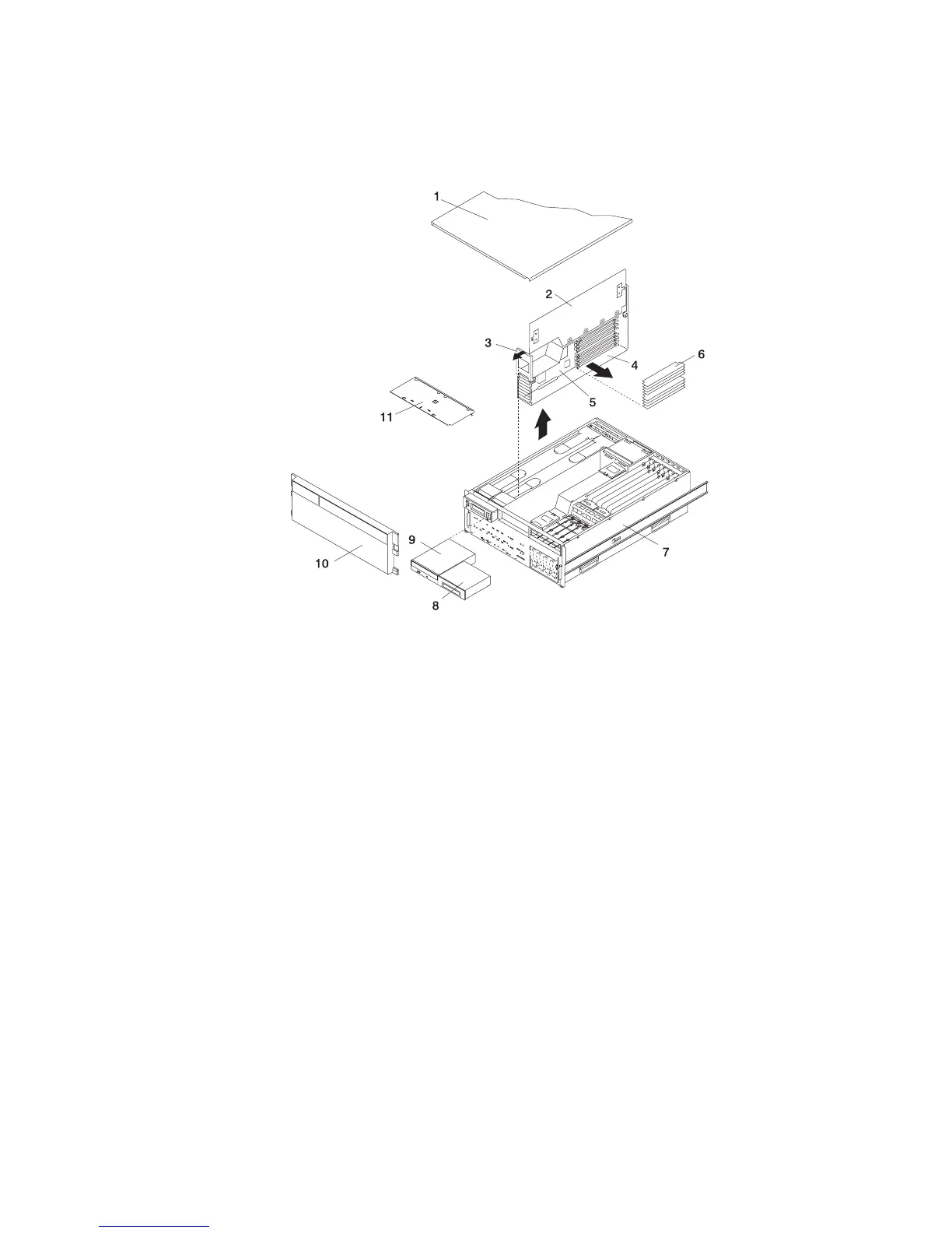
Model 6C4 Memory DIMM
1 Service Access Cover 7 Model 6C4
2 Processor Access Cover 8 Optional Media Device (for example:
Diskette Drive, Tape Drive)
3 Processor Assembly Lifting and
Release Handle
9 IDE CD-ROM Drive
4 Processor Assembly 10 Front Bezel
5 Processor Card 11 Media Device Support Shelf
6 Memory DIMMs
Chapter 9. Removal and Replacement Procedures 493
 Loading...


