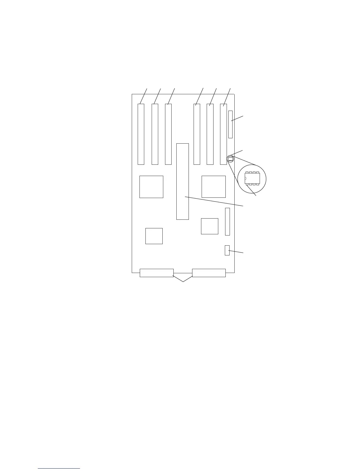
Model D10 I/O Backplane Locations
The following illustration of the I/O backplane identifies the primary connectors used in
your subsystem.
1
2
3
4
5
6
7
8
9
10
11
12
1 PCI adapter connector 1 7 SPCN connector
2 PCI-X adapter connector 2 8 VPD module
3 PCI-X adapter connector 3 9 VPD module pin 1 orientation
4 PCI-X adapter connector 4 10 RIO bus adapter connector
5 PCI-X adapter connector 5 11 Fan connector
6 PCI-X Adapter connector 6 12 Power supply connectors
12 Eserver pSeries 7311 Model D10 and Model D20 Service Guide