D10 Cooling
Fans mounted inside each I/O subsystem power supply and an additional fan mounted
on the front of the subsystem provide cooling. The power supplies and the fan can be
removed and replaced with the power turned on as long as only one is removed from
the I/O subsystem at a time.
D10 Input/Output Ports
The connector ports on the rear of the Model D10 I/O subsystem are used to connect
the RIO cables, the SPCN cables, and the rack-beacon LED.
Subsystem Positioning and Cabling
The I/O subsystem can be installed in a standard 19-inch EIA rack in any location. The
cables that connect the subsystems allow some flexibility in drawer placement, but the
I/O subsystems should be located above the connected processor subsystem in the
same rack.
Up to eight Model D10 I/O subsystems can be connected to a processor subsystem.
Each I/O subsystem is connected to the processor subsystem using a system power
control network (SPCN) cable loop and a remote I/O (RIO) cable loop. One SPCN
cable loop is needed to connect the I/O subsystems to one processor subsystem. Up to
four I/O subsystems are connected to the same processor subsystem using a single
RIO loop.
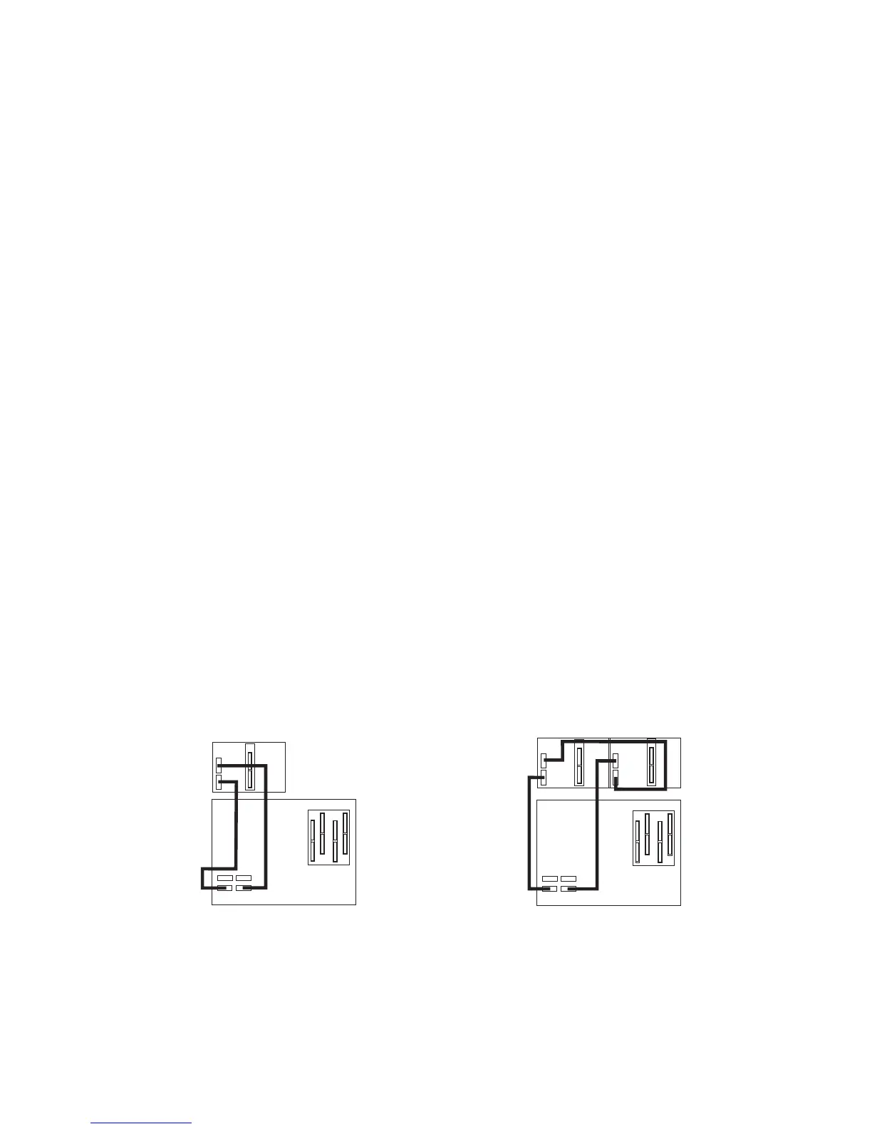
SPCN Cabling
I/O subsystem SPCN cables are connected to the processor subsystem unit using a
loop configuration. The SPCN cables are connected in a loop so that the system has
two paths to each I/O subsystem. A total of eight I/O subsystems are supported on one
SPCN loop.
One I/O Subsystem, Two I/O Subsystems:
The illustration on the left shows one I/O
subsystem connected to the processor subsystem. The illustration on the right shows
two I/O subsystems connected to the processor subsystem using one SPCN loop.
0
1
1
J15
J16
0
1
J15
J16
J15
J16
0
6 Eserver pSeries 7311 Model D10 and Model D20 Service Guide