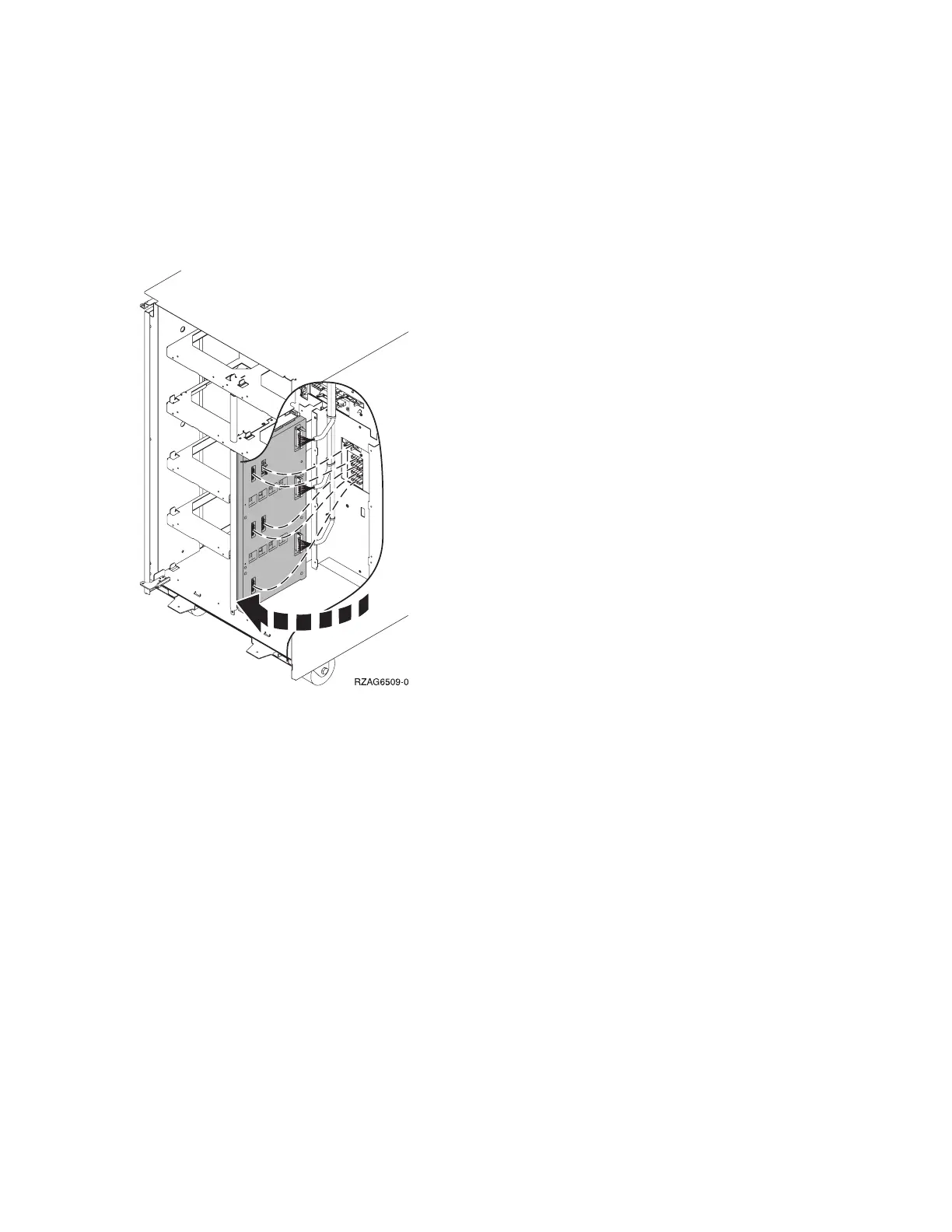
6. Pull the DASD board assembly out until it slides off the guide pins, then rotate the DASD board
assembly 90 degrees. Note the locations of the cables that are located on the backside of the board
assembly, and then remove them.
Note: Both ends of the ribbon cables are marked LH or RH, indicating that one end of the cable is
plugged in to either the left-hand (DB1) or right-hand (DB2) DASD board assembly. The other end of
the cable is plugged in to either the left-most (LH) or right-most (RH) DASD controller card. The cables
will crisscross in the center of the tower.
Figure 1. Device board cabling
7. Remove the DASD board assembly.
8. Install the DASD board assembly by reversing the remove procedure. After exchanging an item, go to
Verify the repair.
This ends the procedure.
FC 5094, FC 9094 - Device board - DB3
For use by authorized service providers.
Use this procedure to remove or replace the device board - DB3 in an FC 5094 or FC 9094.
To remove or replace the device board - DB3:
1. Power off the expansion tower (see Power on/off the system and logical partitions).
2. Disconnect the power cord from the expansion tower.
3. Open the rear cover. See FC 5074, FC 5079, FC 5094, FC 5294, FC 9079, FC 9094 - Covers.
4. From the rear of the expansion tower do the following:
a. Remove the EMC access plate that is located directly above the tower card enclosure. Press the
surfaces of the two latching mechanisms together and tilt the top of the cover away from the frame
to remove it.
b. Remove the cables from the disk unit controller cards (IOAs) that are located inside the PCI card
enclosure and note their locations.
Analyze hardware problems 179