2. This step instructs you how to use the special brush provided with the new processor. It is important
that you follow these instructions very carefully:
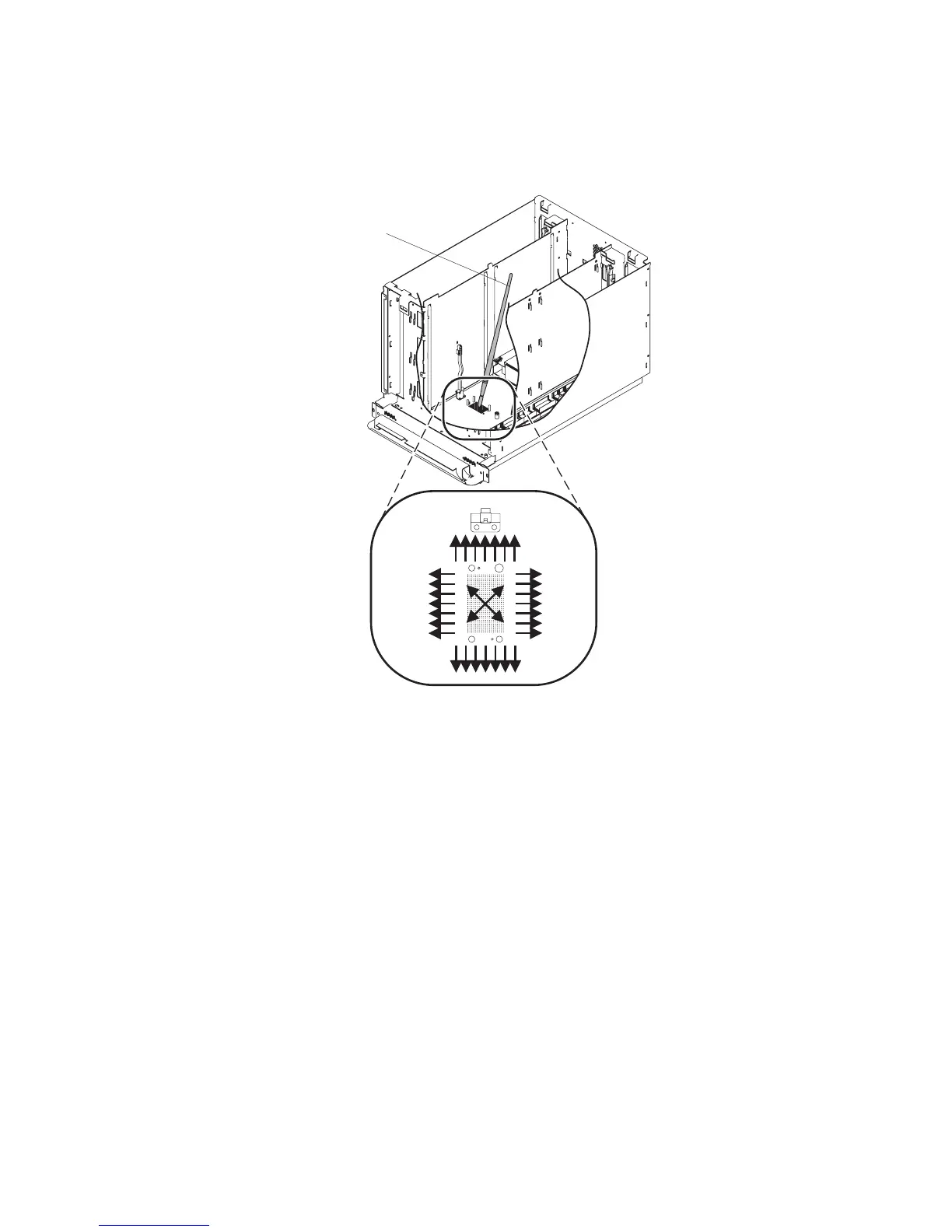
a. Remove the brush from the packaging.
b. Refer to the following figure:
1
c. Starting with the brush (1) in the center of the processor contact surface that is on the CEC
backplane, use an outward brushing motion to clear the debris away from the area where the
surfaces of the processor card and the CEC backplane meet. (Do not brush the processor card or
the contact surface on the bottom of the processor card).
3.
Grasp the center of the new processor card and align the square notch with the processor latch pivot.
The processor latch pivot is on your left as you face the rear of the CEC card-cage. Align the holes in
the processor card with the guide pins on the CEC backplane, and press down until the processor card
is fully seated.
4. Pivot the processor card latch down over the processor card.
5. Insert the spring screw into the end of the processor latch opposite the pivot end (right side, viewed
from the rear of the CEC card-cage). Turn the spring screw clockwise into the threaded hole of the
CEC backplane, then tighten the screw until it stops turning. It is recommended that you use a nut
driver and not a ratchet to tighten the spring screw. This is a compression fitting, so be careful not to
overtighten the spring screw.
Attention: Examine the processor card to see that it is fully seated and make sure that the
processor latch is back to its original position. If it is not fully seated, the processor will fail to function
properly.
6. Complete the replacement by reversing the removal procedures.
Chapter 10. Removal and Replacement Procedures 433
 Loading...


