For SCSI devices, the location code is defined as follows:
AB-CD-EF-G,H
| | | | |
| | | | Logical Unit address of the SCSI Device
| | | Control Unit Address of the SCSI Device
| | Connector ID
| devfunc Number, Adapter Number or Physical Location
Bus Type or PCI Parent Bus
Where:
v AB-CD-EF are the same as non-SCSI devices.
v G defines the control unit address of the device. Values of 0 to 15 are valid.
v H defines the logical unit address of the device. Values of 0 to 255 are valid.
A
bus location code is also generated as ’00-XXXXXXXX’, where XXXXXXXX is equivalent to the node’s
unit address.
Examples of physical location codes and AIX location codes are:
PCI adapter in primary I/O drawer, Slot 1
Location Code U0.1-P1-I1
AIX location Code 20-58
PCI adapter in secondary I/O drawer, Slot 1
Location Code U0.2-P1-I1
AIX location Code E0-58
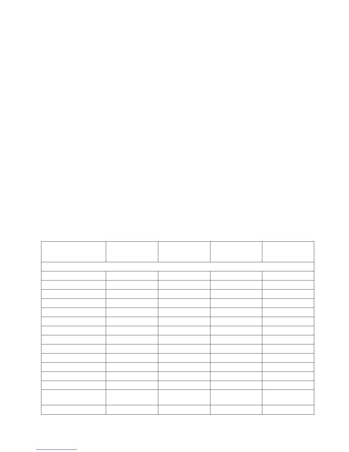
AIX and Physical Location Code Reference Tables
The following tables contain location codes that are used to identify functional units in the RS/6000
Enterprise Server Model M80 and Eserver pSeries 660 Model 6M1 systems. Each table below shows the
locations for a physical part of the system.
FRU Name
Location
Code
AIX
Location
Code
Physical
Connection
Logical
Connection
CEC Drawer 1 Locations
CEC Drawer U1.1
CEC Backplane U1.1-P1 MB1 in CEC
RIO Port 0 Connector U1.1-P1.1/Q1
RIO Port 1 Connector U1.1-P1.1/Q2
RIO Port 2 Connector U1.1-P1.1/Q3
RIO Port 3 Connector U1.1-P1.1/Q4
All RIO Ports U1.1-P1.1
RIO Cable on port 0 U1.1-P1.1/Q1 A0
RIO Cable on port 1 U1.1-P1.1/Q2 A1
RIO Cable on port 2 U1.1-P1.1/Q3 B0
RIO Cable on port 3 U1.1-P1.1/Q4 B1
V/S COMM Connector U1.1-P1.1/Q1
JTAG Connector U1.1-P1/Q2
All Memory (both riser
cards)
U1.1-P1-M1 x2 00-00 CEC Connectors
M02 and M05
Memory Riser Card 1 U1.1-P1-M1 00-00 CEC Connector M02
Chapter 1. Reference Information 31
 Loading...


