3. Unlock and remove the side cover (see “Removing the left-side cover and
bezel” on page 57).
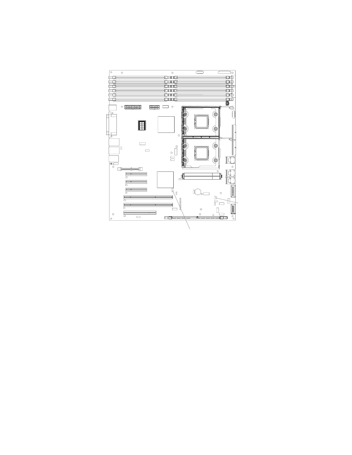
4. Locate SW4 on the system board and remove any adapters that impede
access to the switches.
1
2
3
4
5
6
7
8
9
10
11
12
DIMM LEDs
SW4 (Boot block/Clear CMOS)
SW3
5. Toggle switch 1 (boot block) on SW4 to On.
6. Replace any adapters that you removed; then, install the side cover (see
“Removing the left-side cover and bezel” on page 57).
7. Reconnect all external cables and power cords.
8. Insert the update CD into the CD or DVD drive.
9. Turn on the server and the monitor.
After the update session is completed, remove the CD from the drive and turn
off the server.
10. Disconnect all power cords and external cables.
11. Remove the side cover (see “Removing the left-side cover and bezel” on page
57).
12. Remove any adapters that impede access to the boot block recovery switch.
13. Toggle the jumper of pin 1 (boot block/clear CMOS) on SW4 to Off.
14. Replace any adapters that you removed; then, install the side cover (see
“Removing the left-side cover and bezel” on page 57).
15. Lock the side cover if you unlocked it during removal.
16. Reconnect the external cables and power cords; then, turn on the attached
devices and turn on the server.
The following table describes the function of each switch on the system board.
150 IBM System x3500 Type 7977: Problem Determination and Service Guide

 Loading...


