1. Position the hinge so that the cage would be in the open position if it were
installed in the server.
2. Move the hinge inside the server chassis and align the screw holes with the
holes in the chassis.
3. Secure the cage to the chassis, using three screws.
4. Press on the release tab of the support bracket while you hold the power-supply
cage up with the handle; then, lower the power-supply cage.
5. Press down on the end of the cage until it clicks into place.
6. Close the handle.
7. Replace the power supplies (see “Hot-swap power supply” on page 72).
8. Replace the left-side cover.
9. Reconnect the external cables and power cords.
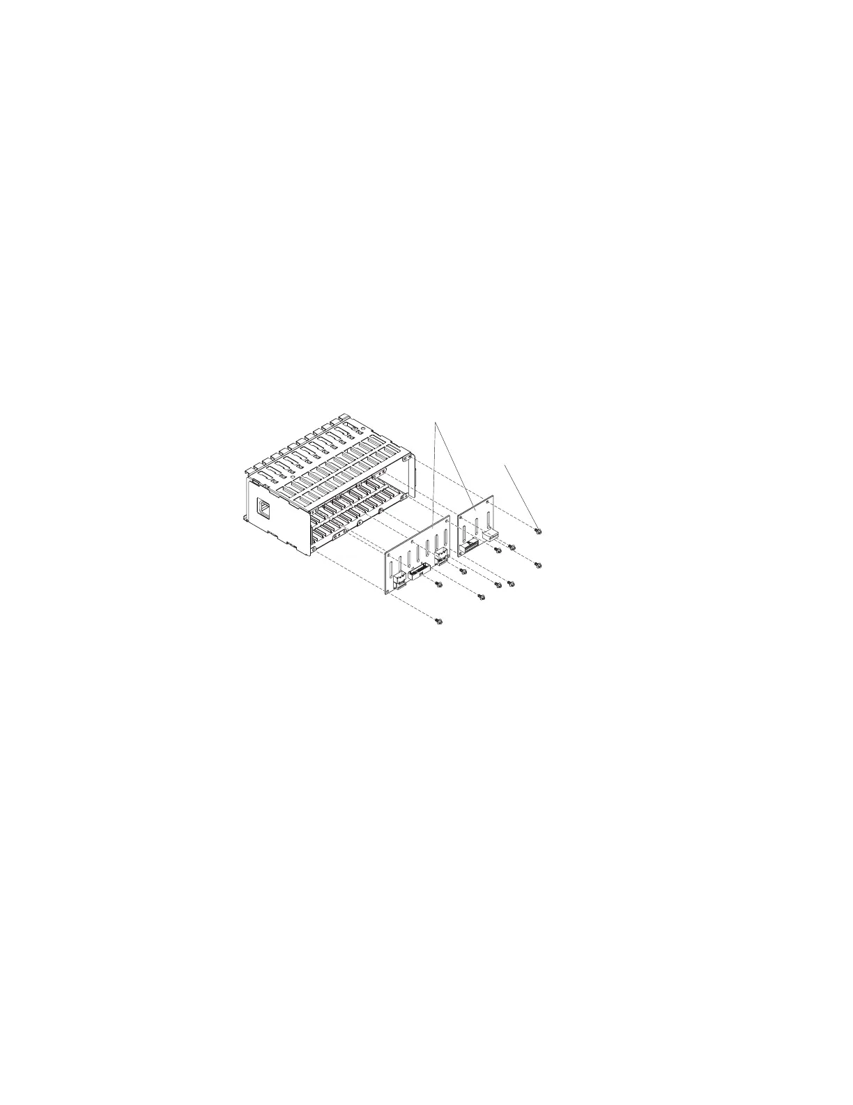
2.5-inch SAS backplane
To remove a 2.5-inch Serial Attached SCSI (SAS) backplane, complete the following
steps.
2.5-inch SAS backplanes
Mounting screws
(x10)
1. Read the safety information that begins on page vii, and “Handling
static-sensitive devices” on page 57.
2. Turn off the server and peripheral devices, and disconnect the power cords
and all external cable as necessary to replace the device.
3. Lay the server on its right side.
4. Remove the left-side cover.
5. Remove the hard disk drives from the server.
6. Remove the fan cage from the server.
7. Note where the SAS signal and power cables are connected to the system
board and the ServeRAID-8s adapter; then, disconnect the SAS signal and
power cables from the system board and the ServeRAID-8s adapter.
Chapter 4. Removing and replacing server components 87

 Loading...


