1 and DIMM connector 4. However, the size, speed, type, and technology of
the DIMMs that you install in DIMM connector 7 and DIMM connector 10 must
match each other.
– The following table shows the DIMM upgrade configuration sequence for
operating in non-mirroring mode (normal mode).
Table 6. 5. DIMM upgrade configuration sequence in non-mirroring mode
Number of DIMMs DIMM connectors
21,4
4 1,4,7,10
6 1, 4, 7, 10, 2, 5
8 1, 4, 7, 10, 2, 5, 8, 11
10 1, 4, 7, 10, 2, 5, 8, 11, 3, 6
12 1, 4, 7, 10, 2, 5, 8, 11, 3, 6, 9, 12
v If a problem with a DIMM is detected, light path diagnostics lights the
system-error LED on the front of the server, indicating that there is a problem,
and guides you to the defective DIMM. When this occurs, first identify the
defective DIMM; then, remove and replace the DIMM.
Removing and replacing memory modules
At least one pair of DIMMs must be installed for the server to operate correctly.
Installing memory modules
DIMMs must be installed in pairs of the same type and speed. To use the memory
mirroring feature, all the DIMMs in the server must be the same type and speed,
and the feature must be supported by your operating system. The following
instructions are for installing one pair of memory modules.
Installing a memory module: To install a memory module, complete the following
steps:
1. Read the safety information that begins on page vii and “Handling
static-sensitive devices” on page 57.
2. Turn off the server and peripheral devices; then, disconnect the power cords
and all external cables necessary to replace the device.
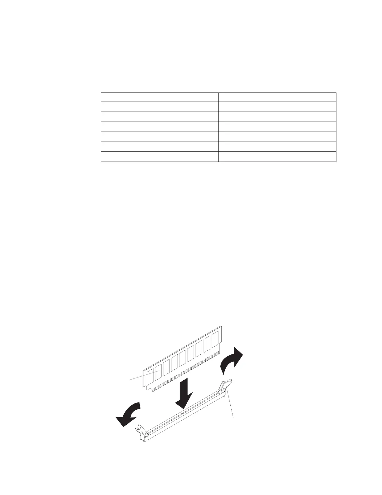
DIMM
Retaining
clip
3. Remove the power supply or power supplies from the server.
70 IBM System x3500 Type 7977: Problem Determination and Service Guide

 Loading...


