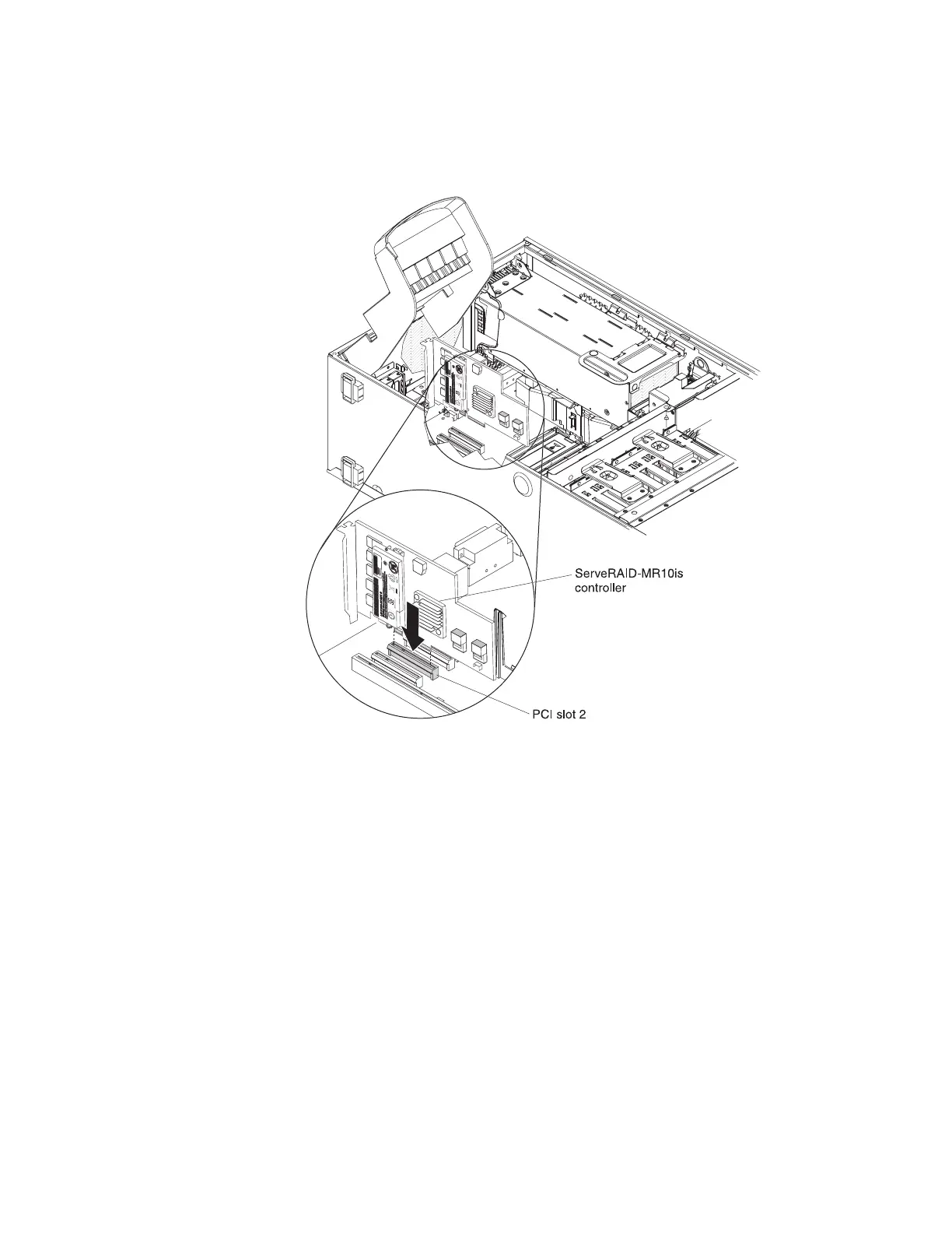
8. Turn the ServeRAID-MR10is adapter so that the ServeRAID-MR10is adapter
keys align correctly with the connector on the system board.
Attention: Incomplete insertion might cause damage to the system board or
the ServeRAID-MR10is adapter.
9. Press the ServeRAID-MR10is adapter firmly into the connector on the system
board.
10. Rotate the power-supply cage assembly out of the chassis:
a. Remove the hot-swap power-supply. Press down on the orange release
lever and pull the power supply out of the bay, using the handle.
b. Lift up the power-supply cage handle and pull the power-supply cage
assembly all the way up until the retainer latch locks the cage in place on
the chassis.
11. Remove the front fan cage assembly (see “Front fan cage” on page 64).
12. Take the other end of the signal cable that is attached to the drive backplane
for drive bays 8 through 11 and route it through the plastic slot on the chassis
underneath the front fan cage; then, connect it to connector J9 on the
ServeRAID-MR10is SAS/SATA controller.
Chapter 4. Removing and replacing server components 83

 Loading...


