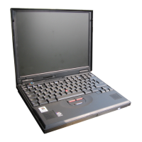
Identifying the hardware features
Rear view of the computer
.1/ The security keyhole is
used with a mechanical
lock.
.2/ The modem connector is
used for connecting your
computer to a telephone
line.
.3/ The power switch turns
the computer on and off.
.4/ The reset switch is used
to power the computer off
if an application hangs or if
the computer does not
accept any input. Use the
tip of a pen to press this
switch.
.5/ The universal serial bus
(USB) connector enables
you to connect any device
that conforms to the USB
interface. Many recent
digital devices comply to
this new standard.
.6/ The power jack is where
the AC Adapter cable is
connected.
.7/ The serial connector is
where you connect a 9-pin,
serial-device cable.
.8/ The system-expansion
connector (240-pin)
enables you to connect a
port replicator.
.9/ The parallel connector is
where you connect a
parallel-printer signal
cable.
.1ð/ The external-monitor
connector is where you
attach an external monitor
(CRT).
.11/ The external-input-device
connector is used to
attach a mouse or an
external numeric keypad to
the computer. An external
keyboard can be attached
to this connector through
an optional
keyboard/mouse cable.
Bottom view of the computer
.1/ The UltraslimBay device
lock is a lock for the
device in the UltraslimBay.
.2/ When the bay LED is on,
the system is in use. Do
not remove a bay device.
.3/ The memory-slot cover
covers the memory slot.
.4/ Each of the memory slots
accepts an SDRAM dual
inline memory module
(DIMM) option.
.5/ The Mini-PCI modem slot
cover covers the modem
card slot.
.6/ The battery-pack latch
locks or releases the
battery pack.
.7/ The serial number label
identifies your computer.
You need this number to
get help.
.8/ Put your name plate here.
.9/ To install or remove the
hard disk, loosen this hard
disk drive screw. You
can use the security screw
shipped with your
computer as a hard disk
screw.
.1ð/ The battery pack is a
built-in power source for
the computer.
Chapter 1. Getting familiar with your computer 5