Number Component Description
2 Control keys The control keys are located to the right of the Operator Panel LCD display on the front of the library.
3 Cartridge
magazine
The tape library has a single cartridge magazine that can hold up to nine data cartridges, or eight data cartridges with a configurable
one-slot I/O station. See Figure 1.
Column 5/Tier 1 in the cartridge magazine can be configured as a one-slot I/O station. Column 5/Tier 2 in the cartridge magazine is
reserved for the exchange position and can be accessed by the library only. The I/O station is used to import and export cartridges
without interrupting normal library operation. Beginning with Column 4, a minimum of one column can be reserved for cleaning
cartridges. Cleaning cartridges are used to clean the tape drive heads. For configuration details, see Installing.
4 Cartridge
magazine
release
Emergency cartridge magazine lock release. When the I/O station is locked, insert a large, straightened paper clip twice or hold the
paper clip in place while the cartridge magazine slides past the I/O station lock.
5 Serial number
label
The machine type and serial number of the library are on the front bezel of the library. The serial number is the number that links the
library to IBM entitlement for service.
6 Air vents These vents draw cooler air into the library enclosure and allow warm air to escape which helps to keep the library at a normal
operating temperature.
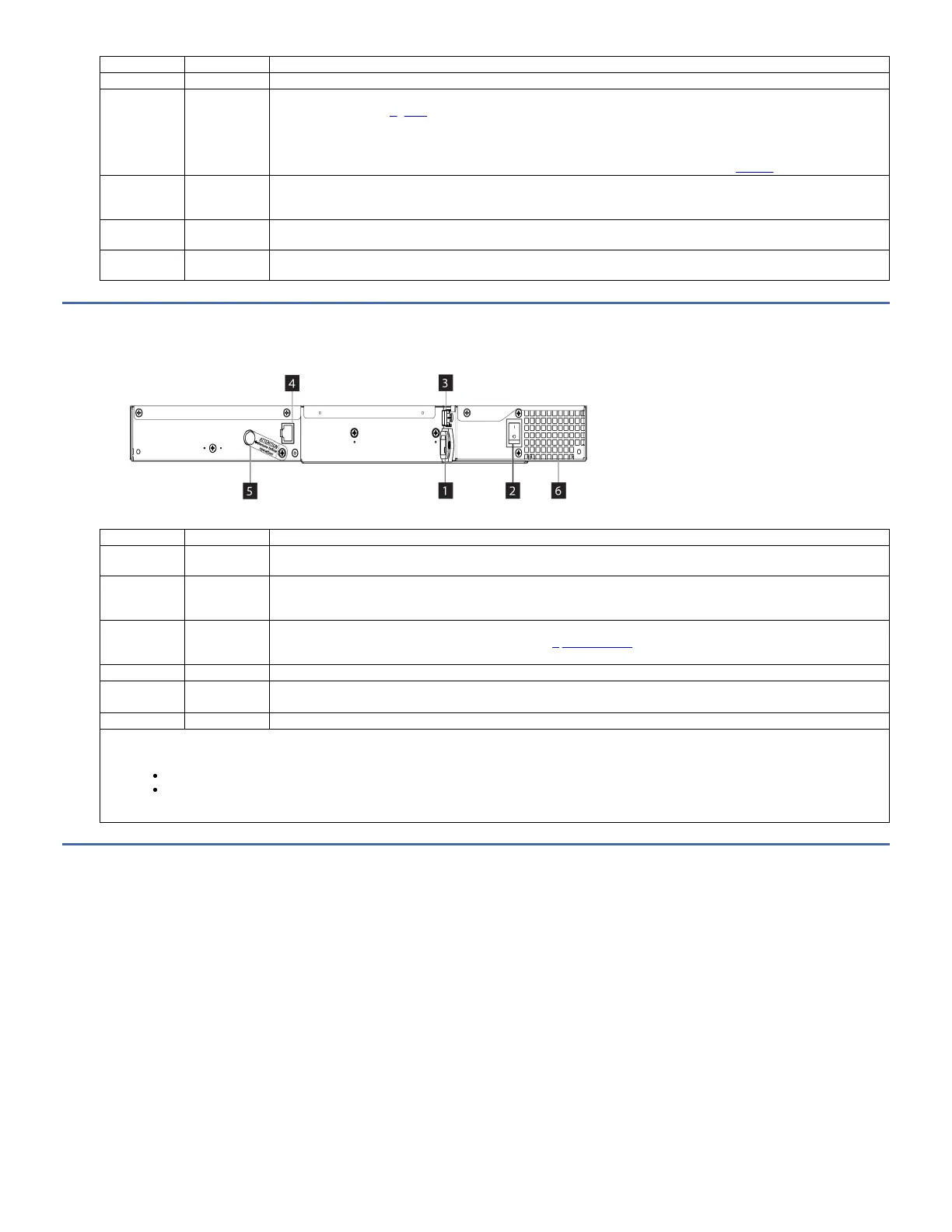
Rear panel
Figure 1. Rear panel components
Table 1. Rear panel component descriptions
Number Component Description
1 Power
connector
The library connects to a 110/220 volt ac power supply.
2
Power switch
1
The library is powered ON/OFF with the power supply switch present on the rear panel. The library has no independent power
switch on the front panel. Before powering OFF the library, ensure that the library is in an idle state with no mechanical movement of
the accessor. Also, ensure that all the data operations like backup operations, accessing of log files are complete.
3 SAS host
interface
connector
Serial-attached SCSI host interface cable connection. The connector type depends on the host bus adapter and the drive
generation. For more information about connector type, see Optional features.
4 Ethernet port This port is used to connect the library to a network.
5 Accessor
locking screw
2
The accessor locking screw is used to lock the accessor in place during transportation.
6 Air vent These vents allow air to escape from the power supply and tape drive sled.
Important:
1.
If you power OFF the library while the library is being accessed, loss of data might occur.
When power cycling the library, wait 10 seconds after the power is turned OFF before the library is powered ON again.
2. Remove the accessor locking screw before the library is powered ON.
Cartridge magazine
The library has a single 10-position removable cartridge magazine, providing a maximum of nine data cartridge positions, or a maximum of eight data cartridge positions
with a configurable 1-slot I/O station. One position is reserved as the tape drive exchange position and can be accessed by the library only.
Figure 1. Cartridge magazine
 Loading...