b. Position of the rotator stub ( 3 ).
c. Front loader motor worm gear ( 1 ). Rotating this gear allows the loader mechanism gear ( 8 ) to
turn.
6. Rotate the loader motor worm gear ( 1 ) to turn the loader mechanism gear ( 6 ) counterclockwise.
Continue turning until the rotator stub ( 3 ) loses contact with the lever ( 7 ). This action releases the
LBA leader pin.
7. Rotate the threader motor worm gear ( 4 ) to turn the threader mechanism gear ( 6 )
counterclockwise. This action moves the LBA out of the cartridge and past the read/write head. Stop
this rotation when the LBA is near the tape guide roller nearest the rear of the drive ( 1 ).
Figure 108. Leader Block Assembly (LBA)
8. Continue rotating the loader motor worm gear ( 1 ) until the rotate stub ( 3 ) is positioned as shown.
Notice that the rotator stub ( 3 ) is nearly aligned with the cartridge loader tray guide bearing ( 2 ).
9. Remove the cartridge from the cartridge loader tray.
10. Go to “Ending procedure” on page 197.
Half height drive: Tape pulled from or broken near leader pin
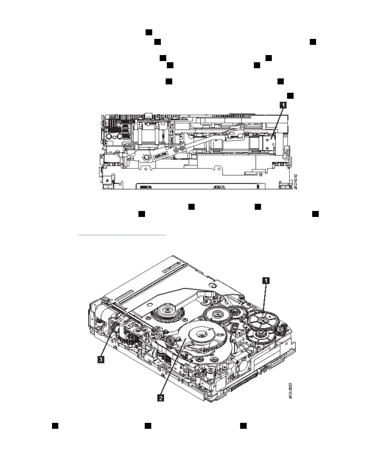
Figure 109. Drive with cover removed to reveal gear train.
1
Threader intermediate
gear
2 Threader mechanism
gear
3 Loader motor worm gear
Appendix D. Manual cartridge removal procedure 185

 Loading...


