13-1
BASIC MANUAL
12
13
13
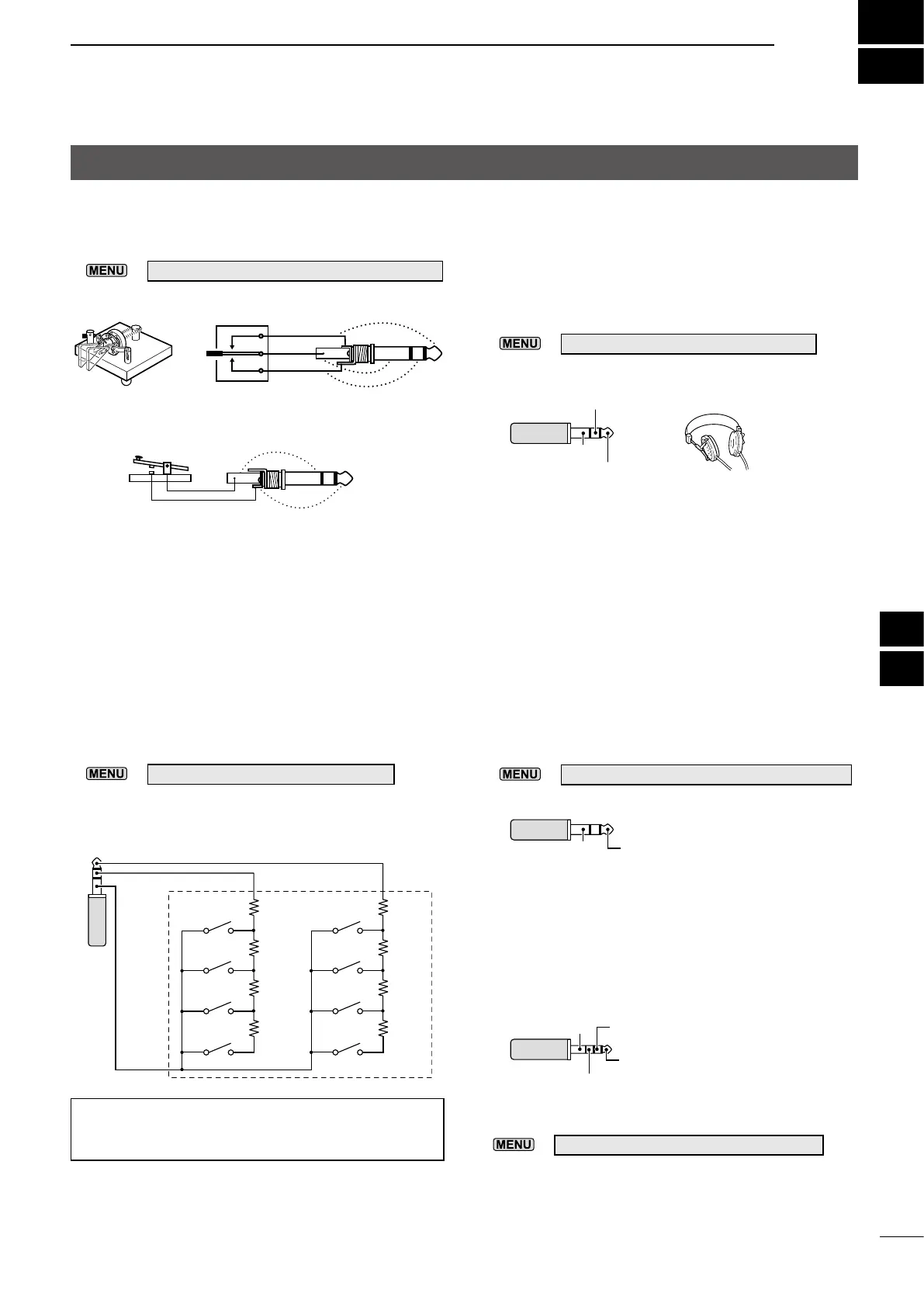
CONNECTOR INFORMATION
D [ELEC-KEY]
Connect a Paddle key or Straight key.
L You can select the key type.
»
KEYER > EDIT/SET > CW-KEY SET > Key Type
By connecting an external keypad to [KEY] with a
circuit as shown below, you can send the content from
one of the 8 memories. You can send the content from
a CW Keyer Memory (M1 ~ M8), SSB/AM/FM/DV/ATV
Voice Memory (T1 ~ T8), or RTTY Memory (RT1 ~
RT8) to be transmitted.
z Push a switch to send the memory content.
z Hold down the switch for 1 second to repeatedly
send the memory content.
L To use the external keypad, turn ON the following item.
»
SET > Connectors > External Keypad
L The external keypad shown below is not supplied by
Icom.
TIP: You can alternate between an external keypad
and a Paddle key or Straight key, when connecting
them in parallel.
D [EXT-SP]
Connect standard stereo headphones or an external
speaker.
The output impedance and output level dier,
depending on the amplier that is used.
L You can change the amplier that is used. Set the
following item according to the connected device.
»
SET > Connectors > SP Jack Function
D [MIC-SP]
Connect a supplied speaker microphone’s speaker
plug.
L You can select the audio output device when the speaker
microphone is connected.
»
SET > Connectors > Speaker MIC AF Output
D [MIC]
Connect a supplied speaker microphone’s plug or an
external microphone’s plug.
* You can select from +3.3 V (through 470 Ω) and +8.0 V
(Maximum 10 mA)
»
SET > Connectors > MIC Jack 8V Output
L Conrm that the transceiver is OFF before connecting or
disconnecting optional equipment.
When using the amplier for a speaker:
• Output impedance: 8 Ω
• Output level: More than 200 mW
(8 Ω load, 10% distortion)
When using the amplier for a headset:
• Output impedance: 16 Ω
• Output level: More than 5 mW
(16 Ω load, 10% distortion)
• Output impedance: 8 Ω
• Output level: More than 200 mW
(8 Ω load, 10% distortion)
3.5 mm (1/8 inch)
Right channel
Left channel
GND
3.5 mm (1/8 inch)
AFGND
2.5 mm
Microphone output + PTT
+3.3 V/+8 V input*
Microphone key output
GND
1.5 kΩ
±5%
1.5 kΩ
±5%
2.2 kΩ
±5%
4.7 kΩ
±
5%
1.5 kΩ
±5%
1.5 kΩ
±5%
2.2 kΩ
±5%
4.7 kΩ
±
5%
S5
S6
S7
S8
S1
S2
S3
S4
External Keypad
_
• Straight key
• Paddle key
3.5 mm (1/8 inch)
3.5 mm (1/8 inch)
dot
com
dash
Controller

 Loading...


