3
1
PANEL DESCRIPTION
01
n
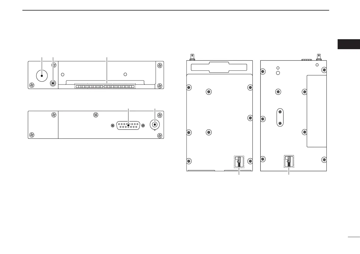
Rear panel
q ANTENNA CONNECTOR
Connect an antenna connector.
w DATA JACK
Connect an optional cloning cable (OPC-1529R) (p. 27).
e DC, MICROPHONE, SPEAKER, HEADPHONE AND
DATA JACK
Connect a 13.8 V or 27.5 V DC power supply, speaker,
headphone and third party GPS receiver*
1
.
Refer to the “INSTALLATION GUIDE” for details.
*
1
Ask your dealer for available GPS receiver details.
n
Main unit
q Metal catch (For Icom products)
Use to attach to an installation rack for Icom products.
w Metal catch (For third party products*)
Use to attach to an installation rack for third party prod-
ucts*.
*Ask your dealer for available products details.
q w
e q
e
For regular type
For the third party* compatible type (MB-113)
*Ask your dealer for available products details.
NOTE: Supplied with some transceiver’s versions.