54
9
CONNECTIONS AND MAINTENANCE
New2001
CAUTION: Transmitting without an antenna may dam-
age the transceiver.
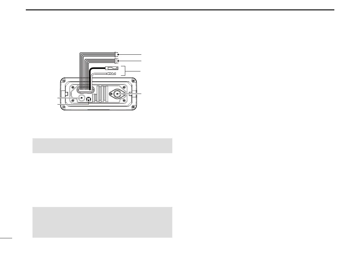
5GROUND TERMINAL
Connects to a vessel ground to prevent electrical shocks
and interference from other equipment occurring.
Use a PH M3 × 6 screw (user supplied).
6GPS ANTENNA CONNECTOR
Connects to the supplied GPS antenna. (For only the
IC-M330G/IC-M330GE)
■ Connections (Continued)
w
q
r
t
y
e
4ANTENNA CONNECTOR
Connects to a marine VHF antenna with a PL-259
connector.
D Connect to the MA-500TR
Connect the transceiver to the high-density D-Sub 15-pin
connector of the MA-500TR using the OPC-2014* cable.
After connecting, an Individual DSC call can be made to
the AIS target using the transponder without entering the
target’s MMSI code.
* The OPC-2014 is supplied with the MA-500TR
• Listener A (Data-H) lead (Yellow):
Connects to lead 3 of the OPC-2014.
• Listener B (Data-L) lead (Green):
Connects to lead 2 of the OPC-2014.
• Talker A (Data-H) lead (White):
Connects to lead 5 of the OPC-2014.
• Talker B (Data-L) lead (Brown):
Connects to lead 4 of the OPC-2014.
NOTE: Be sure the GPS antenna is positioned where
the GPS antenna has a clear view to receive signal from
satellites, and xed using the supplied double-sided
adhesive pad.