New2001
79
New2001
INSTALLATION AND CONNECTIONS
8
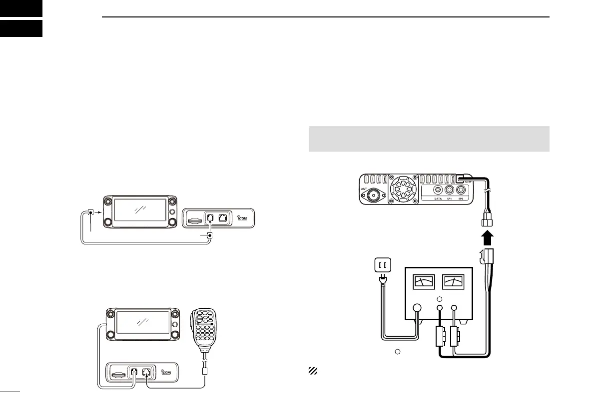
■ Connect controller to main unit
Connect the controller to the main unit with the supplied con-
trol cable.
• The following longer cables may be required, depending on
the installation location.
OPC-440 m i c e x t e n s i o n c a b l e : 5 m (16.4 ft)
OPC-647 m i c e x t e n s i o n c a b l e : 2.5 m (8.2 ft)
OPC-1156 c o n t r o l l e r e x t e n s i o n c a b l e : 3.5 m (11.4 ft)
SP-35 e x t e r n a l s p e a k e r : 2 m (6.5 ft)
SP-35L e x t e r n a l s p e a k e r : 6 m (19.6 ft)
SP-30 e x t e r n a l s p e a k e r : 2.8 m (9.1 ft)
Controller
Main unit
6-pin connector6-pin connector
■ Microphone connection
Plug in the microphone to the microphone connector on the
main unit as shown in the illustration below.
Controller
Main unit
Microphone
■ DC power supply connection
Use a 13.8 V DC power supply with at least 20 A capacity.
Connect the black DC power cable to the (–) Negative termi-
nal, and the red DC power cable to the (+) Positive terminal.
R WARNING! NEVER remove the fuse holders from the
DC power cable.
•CONNECTINGTOADCPOWERSUPPLY
⊕
−
Main unit
to an
AC outlet
DC power
supply 13.8 V
Fuses
20 A
−
⊕
Red Black
See page 83 for a car battery connection.

 Loading...


