83
8
INSTALLATION AND CONNECTIONS
New2001 New2001
RWARNING!
• NEVER remove the fuses from the cable connecting the
transceiver to a power source, such as a car battery.
• NEVER connect the transceiver directly to a 24 V battery.
The transceiver may not receive well on some frequencies
when installed in a hybrid vehicle, or any type of electric ve-
hicle (fuel cell vehicle). This is because vehicle’s electric com-
ponents such as the inverter system generate a lot of electric
noise.
• DO NOT use a cigarette lighter socket as a power source
when operating in a vehicle. The plug may cause voltage
drops and ignition noise may be superimposed onto transmit
or receive audio.
• Use a rubber grommet when passing the DC power cable
through a metal plate to prevent a short circuit.
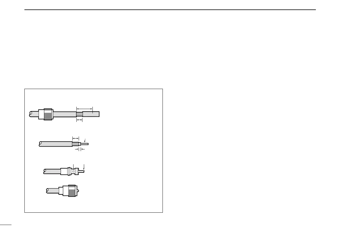
■ Batteryconnection
30 mm
10 mm (Tin)
10 mm
1–2 mm
solder solder
Tin
Coupling ring
PL-259 CONNECTOR INSTALLATION EXAMPLE
q
e
r
w
Slide the coupling ring
down. Strip the cable
jacket and tin the
shield.
Slide the connector
body on and solder it.
Screw the coupling
ring onto the connector
body.
Strip the cable as
shown to the left. Tin
the center conductor.
30 mm (1.18
in) 10 mm (0.39 in) 1–2 mm (0.04–0.08 in)
Antenna installation (Continued) ■
D About Coaxial cable
For radio communications, the antenna is of critically impor-
tance, along with output power and receiver sensitivity.
Select a well-matched 50 ˘ antenna and coaxial cable feed-
line. We recommend 1.5:1 or better Voltage Standing Wave
Ratio (VSWR) on your operating bands.

 Loading...


