2
WHEN CONNECTING TO THE NETWORK THROUGH A PC
18
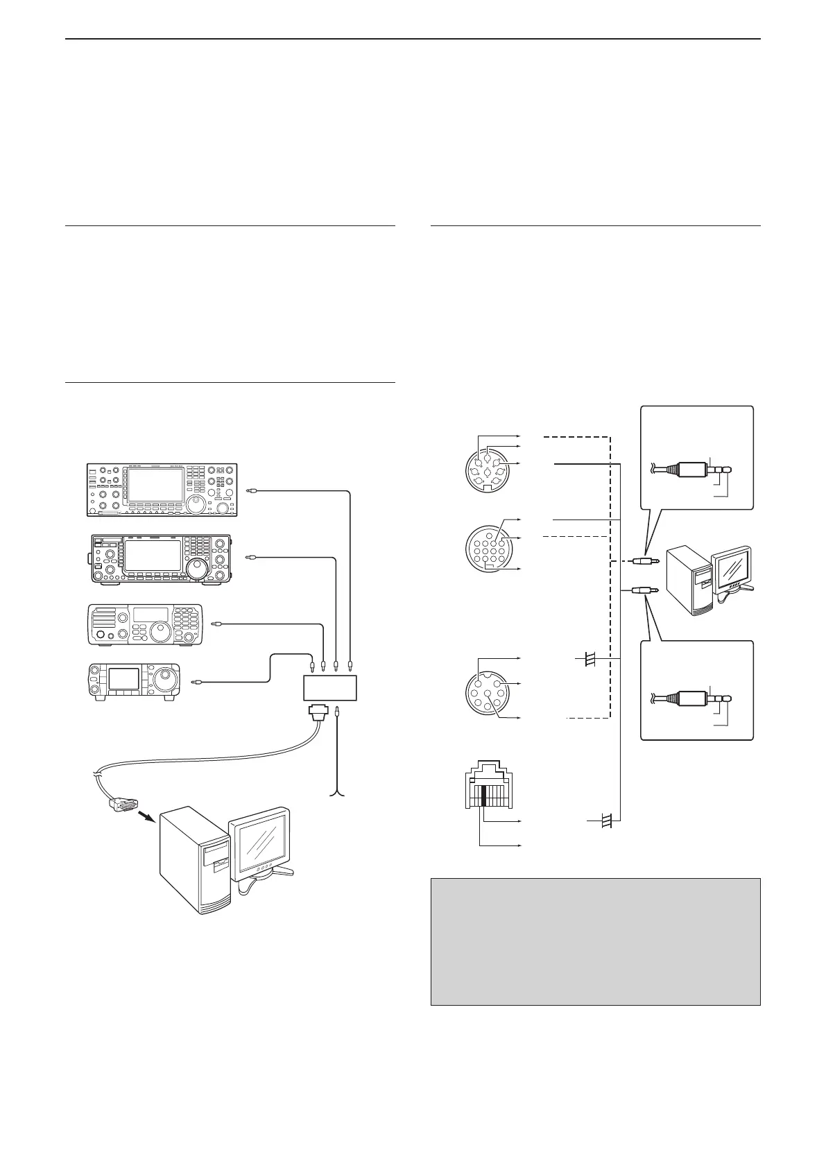
■ Conncting the radio to the Base station’s PC (Continued)
1. System requirements
• A PC that has an RS-232C port
• Icom CI-V command capable radio that has a
[REMOTE] jack
• The optional CT-17
ci-v level converter
(Two mini-plug cables are included.)
• An RS-232C cable (purchase separately)
• Stereo audio cables (purchase separately)
2. Connect a remote control system
Connect the CT-17 to the base station
’s
PC, which
enables the CI-V communication between them.
ct-17
Radio
PC
Mini-plug cable
To an RS-232C port
9–15V DC
To the RS-232C port
RS-232C cable*
3. Connect an audio system
Connect an audio cable between the PC’s audio port
and the radio’s [ACC] socket or [MIC] connector to
enable audio communication between them.
See the radio’s instruction manual for details on the
connector.
Radio PC
AF (Output) LINE IN/MIC IN (Input)
MOD (Input) LINE OUT (Output)
D When connecting to the radio’s [REMOTE] jack
• When using the [MIC] connector, NEVER
directly connect an audio cable between the
radio’s Microphone input and PC. It can cause
a malfunction without adding the Electrolytic
capacitor, as illustrated above.
• NEVER connect a monaural plug to the PC’s
LINE OUT. It can cause a malfunction.
(Rear panel view)
CC] socket
• Connect to the [MIC]
connector
(Front panel view)
(Rear panel view)
IC-7600 type (8 pin)
1
2
3
4
5
6
7
8
MOD
AF
IC-7000 type (13 pin)
1234
8765
9
10 11 12
13
MOD
AF
IC-7600 type (8 pin)
y
IC-7000 type (Modular)
1
2
3
4
5
6
7
8
AF output
iq
PC
GND
MOD
Not used
GND
GND
GND
u
Connect to the
PC’s LINE OUT
GND
AF
Not used
Connect to the
PC’s LINE IN or
MIC IN
Microphone
input
Microphone
input
GND
10 µF/16 V
+
10 µF/16 V
+
* CT-17 accepts only an RS-232C cable. The use of an
RS-232C-USB converter is not guaranteed.