Do you have a question about the ICT KT-LCD7C and is the answer not in the manual?
Diagram showing physical dimensions of the meter.
Diagram showing the wiring connections for the meter.
How to power the meter on and off using the SW button.
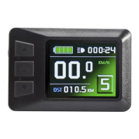
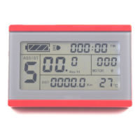
The initial display screen shown upon meter startup.
The second display screen, accessed by pressing SW button.
The third display screen with detailed trip information.
Setting the maximum allowed speed for the electric vehicle.
Setting motor gear reduction ratio and rotor magnet pieces.
Setting the wheel speed pulse signal per revolution.
Selecting power assist control mode (torque or speed).
Configuring handlebar startup mode (zero or non-zero).
Setting power monitoring mode (voltage or smart power).
Setting power assist sensor type and sensitivity.
Setting motor phase classification for sine wave drive.
Initializing power assist ratio gears or setting startup gear.
Configuring handlebar functions like startup mode and speed limits.
Adjusting the controller's maximum current limit.
Adjusting the brightness of the meter's backlight.
Enabling or disabling the cruise control function.
Configuring the display of motor operating temperature.
Setting a password for meter startup.
Option to restore meter settings to factory defaults.
Selecting communication protocol compatibility.
Adjusting the minimum operating voltage threshold.
Configuring ABS braking and energy recovery.
Tuning power-assist strength and gear settings.
Setting the speed for push-assist mode.
Setting under-voltage values for automatic controllers.
Setting for super high-speed motor controllers, related to P1.
Setting for dual mode controllers (Hall sensor failover).
Adjusting the delay time for automatic LCD shutdown.
| Brand | ICT |
|---|---|
| Model | KT-LCD7C |
| Category | Bicycle Accessories |
| Language | English |