EasyManua.ls Logo

Ideal Boilers LOGIC Code Combi 26 - Page 11

Ideal Boilers LOGIC Code Combi 26
64 pages
Print Icon
To Next Page IconTo Next Page
To Previous Page IconTo Previous Page
Loading...
11Ideal Logic Code Combi - Installation and Servicing
GENERAL
General
1. 

2.         

o

3. All components of the system must be suitable for a working
pressure of 3 bar and temperature of 110
o

be taken in making all connections so that the risk of leakage is


a. 
b. 

c. 
d. 

4. ‘Make-up’ Water. 
loss from the system, either :
a. 

above the highest point of the system and be connected
         
  
or
b. 




expansion vessel will be reduced and a larger vessel


or for any other reason, an additional vessel be


Notes
a. The method of lling, relling, topping up or ushing sealed
primary hot water circuits from the mains via a temporary hose
connection is only allowed if acceptable to the local water
authority.
b. Antifreeze uid, corrosion and scale inhibitor uids suitable for
use with boilers having aluminium heat exchangers may be used
in the central heating system.
2
SYSTEM REQUIREMENTS - Central Heating
Water Flow Rate and Pressure Loss
  
 
  
 

o
C 20
(
o
 
  
  
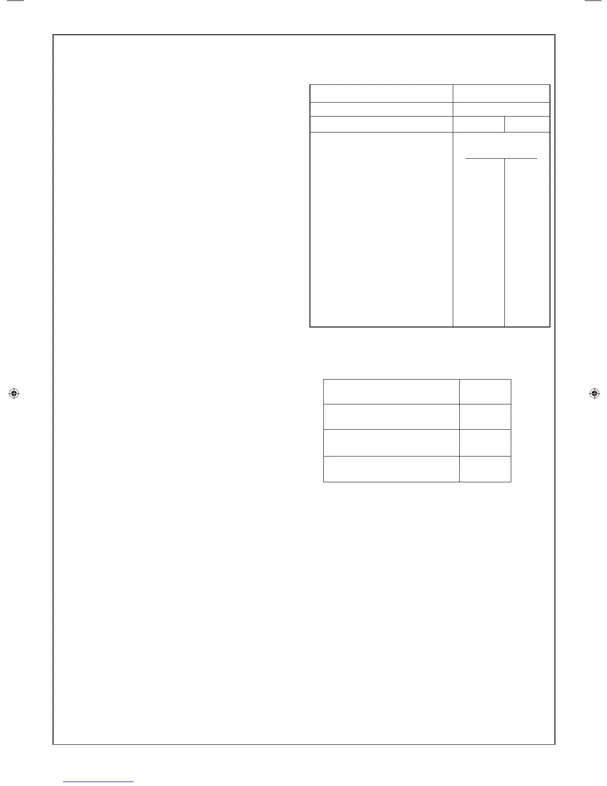
Safety valve setting  
Vessel charge pressure  
System pre-charge pressure   
System volume Expansion vessel
(litres) volume (litres)
  
  
  
  
  
  
  
  
  
  
  
For other system volumes
multiply by the factor across  
5. Filling

Where the mains pressure is excessive a pressure

a. 

b. Fill and vent the system until the pressure gauge


c. Check the operation of the safety valve by raising the


d. Release water from the system until the
minimum system design pressure is reached;

continued . . . . . .
206279-1.indd 11 06/01/2011 09:09:40

Related product manuals