14
Installation and Servicing
SECTION 1 - GENERAL
General
1. The installation must comply with all relevant national and local
regulations.
2. The installation should be designed to work with flow
temperatures of up to 84
o
C.
3. All components of the system must be suitable for a working
pressure of 300kPa and a maximum design temperature of 110
o
C. Extra care should be taken in making all connections so that
the risk of leakage is minimised.
The following components are incorporated within the appliance:
a. Circulating pump.
b. Safety valve, with a non-adjustable preset lift pressure of
300kPa.
c. Pressure gauge, covering a range of 0 to 400kPa.
d. An 8-litre expansion vessel, with an initial charge pressure
of 75kPa.
4. Filling Water Connection. Mains water ll lines must be installed
with an Automatic Filling Valve - Available from Hunt Heating. After
following the below lling instructions the Automatic Filling Valve
MUST be turned off.
The maximum cold water capacity of the system should not exceed
143 litres. This is the maximum system volume for the boiler
expansion vessel. If the capacity of the vessel is not considered
sufcient for this, or for any other reason, an additional vessel MUST
be installed on the return to the boiler.
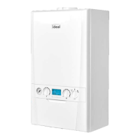
Guidance on vessel sizing is given in table opposite.
5. Filling
After installation of an Autoll valve and required backow prevention,
the system may be lled by the following method:
i. Thoroughly ush out the whole system with cold water.
ii. Fill and vent the system until the pressure gauge registers
150kPa, and examine for leaks.
iii. Check the operation of the safety valve by raising the water
pressure until the valve lifts. This should occur within 30kPa of the
preset lift pressure.
iv. Release water from the system until it reaches 100kPa. Isolate
main water supply by turning off autoll valve.
Notes
a. The method of lling, relling, topping up or ushing sealed
primary hot water circuits from the mains via a temporary hose
connection is only allowed if acceptable to the local water
authority.
b. Antifreeze uid, corrosion and scale inhibitor uids suitable for
use with boilers having aluminium heat exchangers may be used
in the central heating system.
1.18 SYSTEM REQUIREMENTS - CENTRAL HEATING
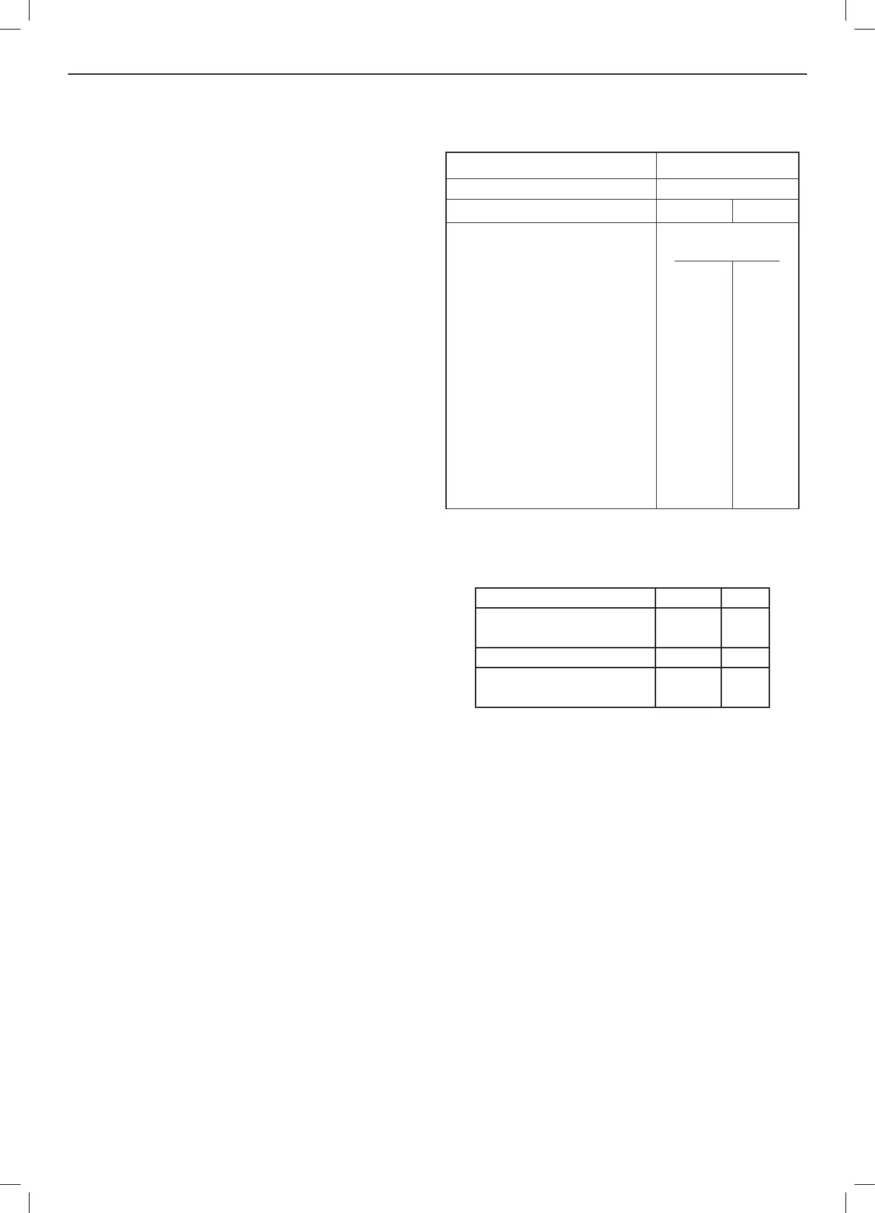
Water Flow Rate and Pressure Loss
Safety valve setting kPa 300
Vessel charge pressure kPa 50 to 75
System pre-charge pressure kPa None 100
System volume Expansion vessel
(litres) volume (litres)
25 1.6 1.8
50 3.1 3.7
75 4.7 5.5
100 6.3 7.4
125 7.8 9.2
150 9.4 11.0
175 10.9 12.9
190 11.9 14.0
200 12.5 14.7
250 15.6 18.4
300 18.8 22.1
For other system volumes
multiply by the factor across 0.063 0.074
continued . . . . . .
Max CH Ouput kW 24.2
Water Flow Rate
l/min 17.3
(gal/min) (3.8)
Temperature Differential °C 20
Head available for system
kPa 33.33
(ft.w.g.) (11.1)