24
Installation and Servicing
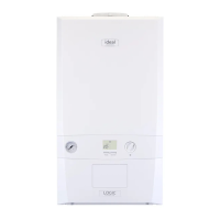
FLUE OUTLET
SECTION 2 - INSTALLATION
100mm
to outside face of wall plus
44mm = ue length
Centre of turret to edge of turret = 100mm
Turret has a ue insertion of 30mm
The compressed outer wall seal has protruding wall to seal mounting lip - 14mm
From centreline of turret to wall. Rear mount 155mm, side (including clearance) 200mm
NOTES
REAR
Fit
to wall
A
WALL
Flue length measured from outer terminal lip
to end of outer ue
A + 44mm
to outside face of wall plus
44mm = ue length
SIDE
Fit
to wall
A
WALL
Minimum clearance 5mm
....... DETERMINING THE FLUE LENGTH AND FLUE PACKS REQUIRED, CONT’D
FIGURE 1
Note. Maximum permissible
ue length is measured from
centre line of appliance ue
outlet to outside wall face.
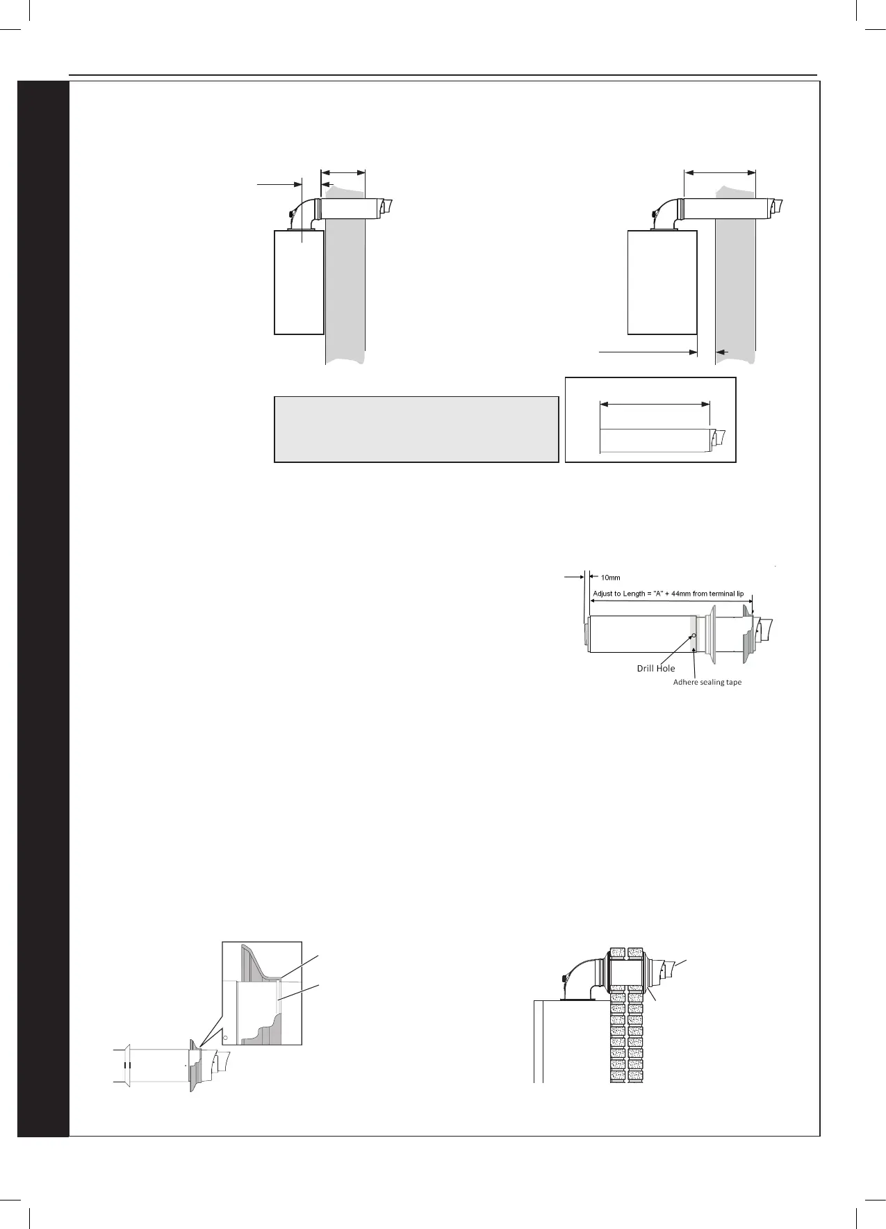
2.14 CUTTING & SETTING THE FLUE LENGTH
SETTING TELESCOPIC FLUE B PACKS
1. Measure the required ue length (A+44mm).
2. Measure from the outer terminal lip to end of outer ue. Pull apart ue until
desired length is achieved. ENSURE THE STOP MARK IS NOT VISIBLE, IF
IT IS, THE FLUE IS TOO SHORT AND SHOULD NOT BE USED.
3. Check that both ue seams are at the top and the outlet terminal is uppermost.
4. Drill a 3.5mm hole through one of the 2 outer side holes in the outer ue
section into the inserted outer ue (as shown). Take care not to pierce the
inner plastic ue. Fit screw provided.
5. Seal the joint on the outer air duct with the tape provided.
6. Fit internal and external wall seals (see installing ue).
2.15 INSTALLING THE FLUE (INTERNAL BOILER)
FITTING FLUE THROUGH THE WALL
1. Fit external black wall seal ensuring the inside of the outer lip is in contact with the terminal lip you have been measuring from
(see g 1).
2. Place the ue through the wall.
3. Fit the internal wall seal.
4. Ensure the seam and the outlet terminal are at the top and tted as shown.
Ensure lip of wall seal is positioned
over step on plastic nose of flue terminal
(note, seal is cut away for clarity)
Terminal Lip
Wall Seal Lip
Rubber
Terminal
Wall Seal
Terminal
MUST be
fitted as
shown
Fig 1
continued . . . . . .