51
Installation and Servicing
SECTION 3 - SERVICING
SERVICING
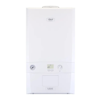
3.21 DHW FLOW TURBINE SENSOR REPLACEMENT
1. Refer to Section 3.9.
2. Drain the DHW system. Refer to Section 3.22.
3. Pull off the electrical connection.
4. Using a suitable tool, lift and remove the retaining clip.
5. Use the clip to ease the turbine sensor from its housing.
6. Re-assemble in reverse order.
7. Check that the boiler operates in both DHW & CH modes.
4
3
5
3.22 DRAINING THE BOILER
DOMESTIC HOT WATER CIRCUIT
1. Refer to Section 3.9.
2. Close all the DHW water isolating valves on the boiler inlet.
3. To drain the domestic hot water circuit: As there is no direct drain for the domestic hot water circuit, depending on the location
of the boiler, opening the lowest hot water tap may drain this circuit. However it must be noted that some residual water will be
experienced during replacement of components.
4. After replacing any component on the boiler, close tap, close the drain valve and open all system isolating valves (re-pressurise
as appropriate, refer to Section 2.19) before proceeding to check operation of the boiler.
5. Disconnect lling loop. Refer to Section 2.19.
6. Check that the boiler operates in both DHW & CH modes.
CENTRAL HEATING CIRCUIT
1. Refer to Section 3.9.
2. Close all the CH water isolating valves on the boiler inlet.
3. To drain the primary heat exchanger circuit: Open the drain valve
and attach a length of hose to the CH drain point.
4. After replacing any component on the boiler, remove the hose,
close the drain valve and open all system isolating valves (re-
pressurise as appropriate by re-connecting the lling loop, refer to
Section 2.19) before proceeding to check operation of the boiler.
5. Disconnect lling loop. Refer to Section 2.19.
6. Check that the boiler operates in both DHW & CH modes.
1. Refer to Section 3.9.
2. Drain the heating system. Refer to Section 3.22.
3. Remove the boiler front (See Section 3.2), lower the control
panel and remove the control box cover.
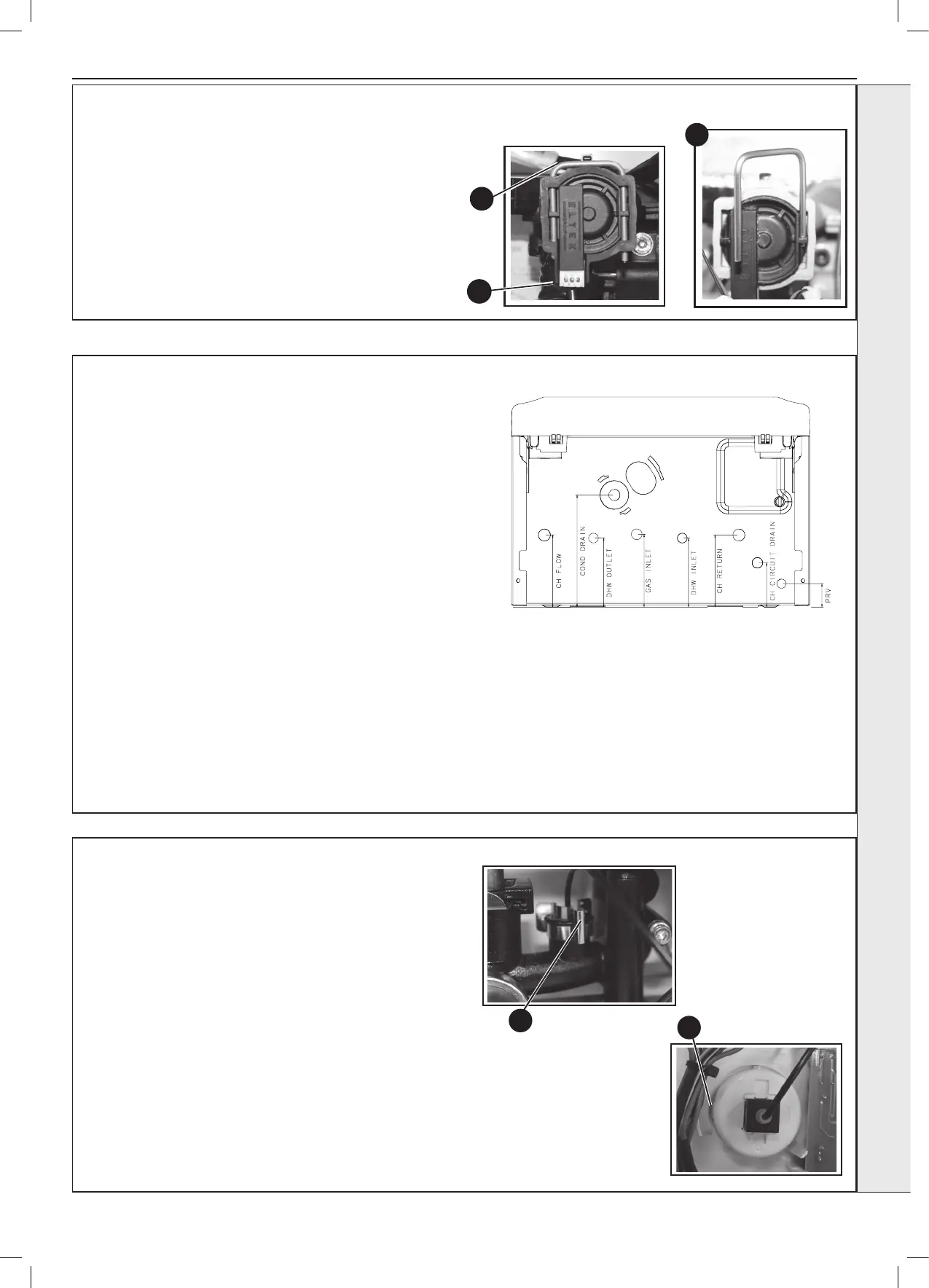
4. Ensuring there is no pressure in the system unclip the C
clip from the ow manifold port and remove the capillary
connection together with ‘o’ ring.
5. Releasing the two retaining clips on the pressure gauge
ease the pressure gauge through the front of the control
panel.
6. Fit the new pressure gauge from the front of the control
panel ensuring correct orientation. Locate push t
connection into port ensuring ‘o’ ring in place and secure
with the C clip.
7. Rell the boiler. Refer to Section 2.19.
8. Check that the boiler operates in both DHW & CH modes.
3.23 PRESSURE GAUGE REPLACEMENT
4
5