27
Installation and Servicing
SECTION 2 - INSTALLATION
INSTALLATION
2.18 CONDENSATE DRAIN
This appliance is tted with a siphonic 75mm condensate trap
system that requires lling before operating the appliance for the
1st time or after maintenance.
All condensate pipework should conform to the following:
a. Where a new or replacement boiler is being installed, access to
an internal ‘gravity discharge’ termination should be one of the
main factors considered in determining boiler location.
b. Plastic with push t or solvent connections.
c. Internal plastic pipe work a minimum of 19mm ID (typically
22mm OD).
d. External plastic pipe must be a minimum of 30mm ID (typically
32 OD) before it passes through the sleeved wall.
e. All horizontal pipe runs must fall a minimum of 45mm per metre
away from the Boiler.
f. External & unheated pipework should be kept to a minimum and
insulated with Class “O” waterproof pipe insulation.
g. All installations must be carried out in accordance to the
relevant connection methods as shown in the “Condensate
installation diagrams” & BS6798.
h. Pipework must be installed so that it does not allow spillage into
the dwelling in the event of a blockage (through freezing)
i. All internal burrs should be removed from the pipe work and any
ttings.
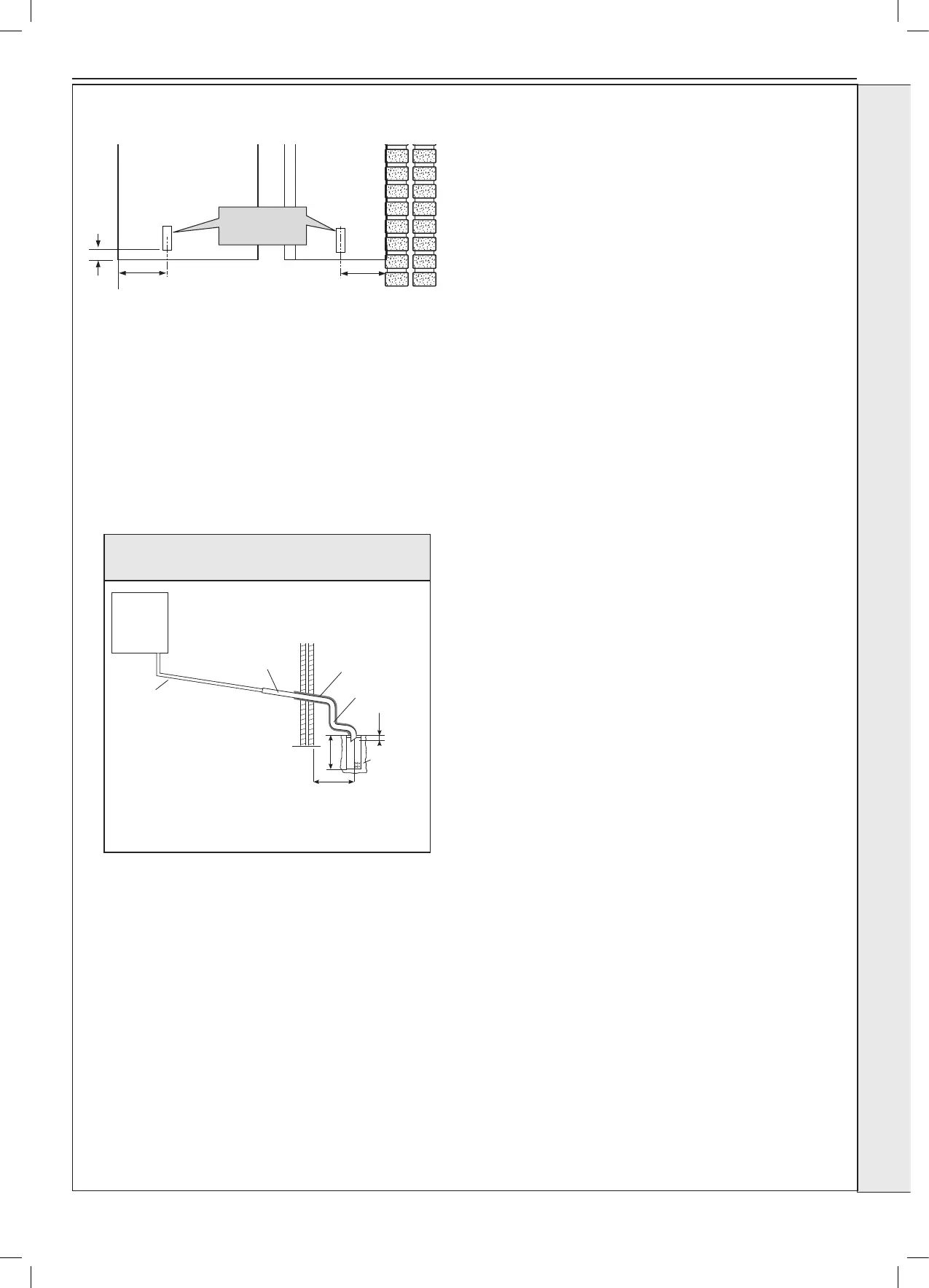
Boiler
with 75mm
sealed
condensate
trap
Min Ø 19mm
Internal pipe
Min Ø 30mm
Internal pipe
Water/Weather
proof insulation
Max 3m external
pipework
Limestone
chippings
≥ 500
≥ 300
≥ 25
2 rows of three Ø12mm holes
25mm centres, 50mm from
the bottom of the tube, facing
away from the house
Connection of a Condensate Drainage Pipe to an External
Purpose Made Soakaway.