25
Installation and Servicing
FLUE OUTLET
SECTION 2 - INSTALLATION
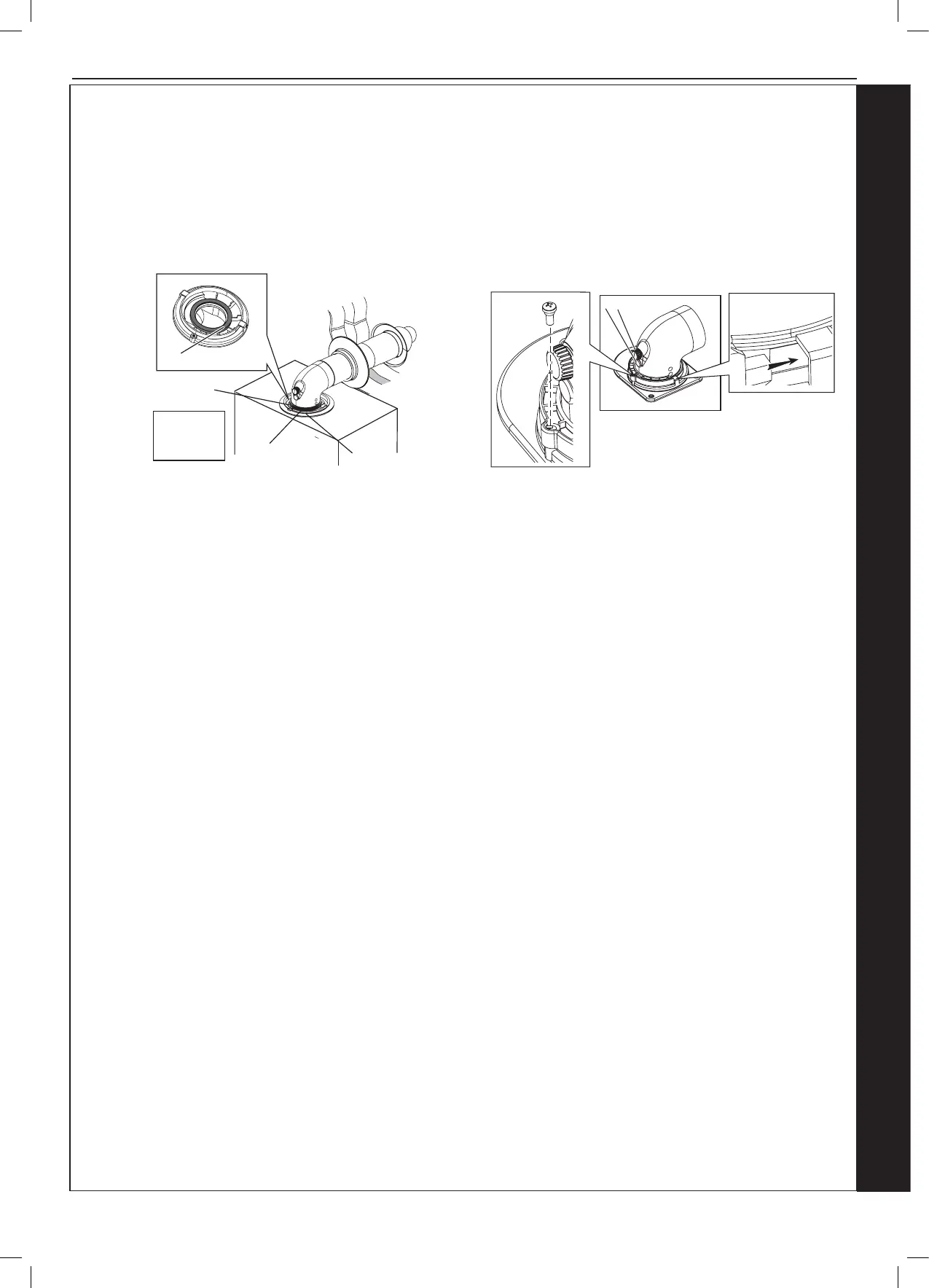
FITTING THE TURRET - Ensure the condense trap/siphon is lled with water
1. Ensure the rubber seal is tted correctly on the appliance manifold and that all ue seals are undamaged.
2. Hold the ue rmly and push the turret on until it has travelled 30mm on to the ue pipe and is fully engaged. Make sure the
ue has not rotated or moved forward during tting and the ue seam is uppermost.
3. Push the turret into the manifold ensuring the upper plastic lip is ush with the top of the manifold.
4. Fully engage the clamp location section into the manifold location holes. Rotate down on to turret ange.
5. Secure clamp to appliance using securing screw.
6. Ensure all sample points are accessible and all sample plugs and caps are tted.
Retaining
screw
Clamp Lugs
Sample points
Flue Outlet
C
A
A - Duct Assembly
B - Flue Turret
C - Turret Clamp
D - Seal
Flue Outlet
D
B
Note.
A at or pitched roof ashing plate (not supplied) is required before proceeding
with the installation of this kit.
This kit is suitable for both at and pitched roof terminations, using a concentric
ue to run vertically from the top of the boiler and terminating above roof level.
Connection to the top of the boiler is made using the supplied vertical
connector.
ACCESSORIES
Flue Duct Extension Kits are available for ue lengths extending beyond 1m.
These packs contain 500mm, 1000mm or 2000mm extension ducts and may
be cut to the desired length.
If the offset vertical option is used an Elbow Kit is required.
2.16 FITTING THE OPTIONAL ROOF FLUE KIT