6: M
ODBUS
C
OMMUNICATION
6-8 FC6A S
ERIES
M
ICRO
S
MART
A
LL
-
IN
-O
NE
T
YPE
C
OMMUNICATION
M
ANUAL
FC9Y-B1730
Modbus RTU Slave Communication
Modbus slave communication can be configured by selecting Modbus RTU Slave for Port 1, Port 2 and Port 3 in the WindLDR
Function Area Settings. When a Modbus RTU slave receives a request from the Modbus RTU master, the Modbus RTU slave
reads or writes data according to the request. The request is processed at the END processing of the user program.
Modbus RTU slaves do not reply to the Modbus RTU master for the broadcast requests.
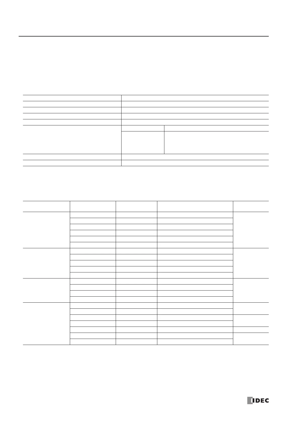
Modbus RTU Slave Communication Specifications
*1 When timeout occurs, the FC6A Series MicroSmart discards the received data and waits for the first frame of the next valid communication.
*2 For communication at 19,200 bps or higher, the timeout between characters needs to be a minimum of 0.75 ms.
*3 For communication at 19,200 bps or higher, the timeout between frames needs to be a minimum of 1.75 ms.
Map of Slave Addresses for Modbus RTU Slaves
*1 Addresses generally used for Modbus communication. "Calculating Modbus Addresses for FC6A Series MicroSmart Devices" on page 6-9 shows
the method to calculate slave addresses from FC6A Series MicroSmart devices.
*2 These 4-digit addresses are used in the communication frame. To calculate the address used in communication frame, extract lower 5 digits of
the Modbus address, subtract 1 from the value, and convert the result into hexadecimal.
*3 Access within the device range for the FC6A Series MicroSmart type used.
Item Description
Baud Rate (bps) 9,600, 19,200, 38,400, 57,600, 115,200
Data Bits 8 bits (fixed)
Stop bits 1, 2 bits
Parity Odd, even, none
Slave Number
Constant 1 to 247
Data register
Set the special data register values between 1 and 247
Port 1: D8100
Port 2: D8102
Port 3: D8103
Timeout between Characters
*1
1.5 characters minimum
*2
Timeout between Frames
*1
3.5 characters minimum
*3
Modbus Device Name
Modbus Address
Map (Decimal)
*1
Communication
Frame Address
*2
FC6A Series MicroSmart Device
*3
Applicable
Function Code
Coil
(000000 and above)
000001 - 000504 0000 - 01F7 Q0 - Q627
1, 5, 15
000701 - 000956 02BC - 03BB R000 - R255
001001 - 003048 03E8 - 0BE7 M0000 - M2557
003049 - 007400 0BE8 - 1CE7 M2560 - M7997
009001 - 009256 2328 - 2427 M8000 - M8317
011001 - 017000 2AF8 - 4267 M10000 - M17497
Input Relay
(100000 and above)
100001 - 100504 0000 - 01F7 I0 - I627
2
101001 - 101256 03E8 - 04E7 T000 - T255 (timer contact)
101501 - 101756 05DC - 06DB C000 - C255 (counter contact)
102001 - 102768 07D0 - 0ACF T256 - T1023 (timer contact)
104001 - 104256 0FA0 - 109F C256 - C511 (counter contact)
Input Register
(300000 and above)
300001 - 300256 0000 - 00FF T000 - T255 (timer current value)
4
300501 - 300756 01F4 - 02F3 C000 - C255 (counter current value)
302001 - 302768 07D0 - 0ACF T256 - T1023 (timer current value)
304001 - 304256 0AF0 - 10A0 C256 - C511 (counter current value)
Holding Register
(400000 and above)
400001 - 408000 0000 - 1F3F D0000 - D7999
3,6,16
408001 - 408500 1F40 - 2133 D8000 - D8499
409001 - 409256 2328 - 2427 T000 - T255 (timer preset value)
3
409501 - 409756 251C - 261B C000 - C255 (counter preset value)
410001 - 456000 2710 - DABF D10000 - D55999 3,6,16
462001 - 462768 F230 - F52F T256 - T1023 (timer preset value)
3
464001 - 464256 FA00 - FAFF C256 - C511 (counter preset value)