5: U
SER
C
OMMUNICATION
I
NSTRUCTIONS
5-16 FC6A S
ERIES
M
ICRO
S
MART
A
LL
-
IN
-O
NE
T
YPE
C
OMMUNICATION
M
ANUAL
FC9Y-B1730
• Multi-byte start delimiter
First two bytes can be configured as a multi-byte start delimiter. The incoming data is processed according to the receive format
only when the first two bytes of the incoming data match the start delimiter. Therefore, only the incoming data sent to slave
station 1 is processed. No extra ladder programming is needed to check the slave station number.
Designating Constant as End Delimiter
An end delimiter can be programmed at the end of the receive format of a RXD instruction; the FC6A Series MicroSmart will
recognize the end of valid communication, although RXD instructions without an end delimiter can also be executed.
When a constant value is designated at the end of source device S1, the one-byte data serves as an end delimiter to end the
processing of the received data. If data bits are set to 7 bits, the end delimiters will be between 00h and 7Fh. If data bits are set
to 8 bits, the end delimiters will be between 00h and FFh. Constant values are entered in character or hexadecimal notation into
the source data. When using the same RXD instruction repeatedly in a user program, assign different end delimiters for each RXD
instruction.
If a character in incoming data matches the end delimiter, the RXD instruction ends receiving data at this point and starts
subsequent receive processing as specified. Even if a character matches the end delimiter at a position earlier than expected, the
RXD instruction ends receiving data there.
If a BCC code is included in the receive format of a RXD instruction, an end delimiter can be positioned immediately before or after
the BCC code. If a data register or skip is designated between the BCC and end delimiter, correct receiving is not ensured.
When a RXD instruction without an end delimiter is executed, data receiving ends when the specified bytes of data in the receive
format, such as data registers and skips, have been received. In addition, data receiving also ends when the interval between
incoming data characters exceeds the receive timeout value specified in the Communication Parameters dialog box whether the
RXD has an end delimiter or not. The character interval timer is started when the first character of incoming communication is
received and restarted each time the next character is received. When a character is not received within a predetermined period of
time, timeout occurs and the RXD ends data receive operation.
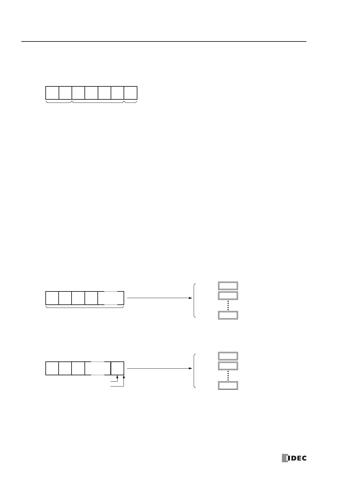
Example:
(1) When a RXD instruction without an end delimiter is executed
(2) When a RXD instruction with end delimiter ETX (03h) and without BCC is executed
STX
(02h)
“1“
(31h)
Start
Delimiter
(3xh)
(3xh)
(3xh)
(3xh)
CR
(13h)
Stored to D1
End
Delimiter
****
h
D100
When D100 is designated
“0”
(30h)
“1”
(31h)
Total of received characters
“2”
(32h)
“3”
(33h)
Incoming Data
****
h
D100+n
****
h
D101
The incoming data is divided, converted, and stored to data registers according to the receive format.
Receive operation is completed when the total characters programmed in RXD are received.
as the first data register
****
h
D100
When D100 is designated
ETX
(03h)
“1”
(31h)
End Delimiter
“2”
(32h)
“3”
(33h)
Incoming Data
****
h
D100+n
****
h
D101
The incoming data is divided, converted, and stored to data registers according to the receive format.
The end delimiter is not stored to a data register.
Any data arriving after the end delimiter is discarded.
as the first data register
End of receiving data