2: P
RODUCT
S
PECIFICATIONS
2-94 FC6A S
ERIES
MICROS
MART
U
SER
’
S
M
ANUAL
FC9Y-B1722
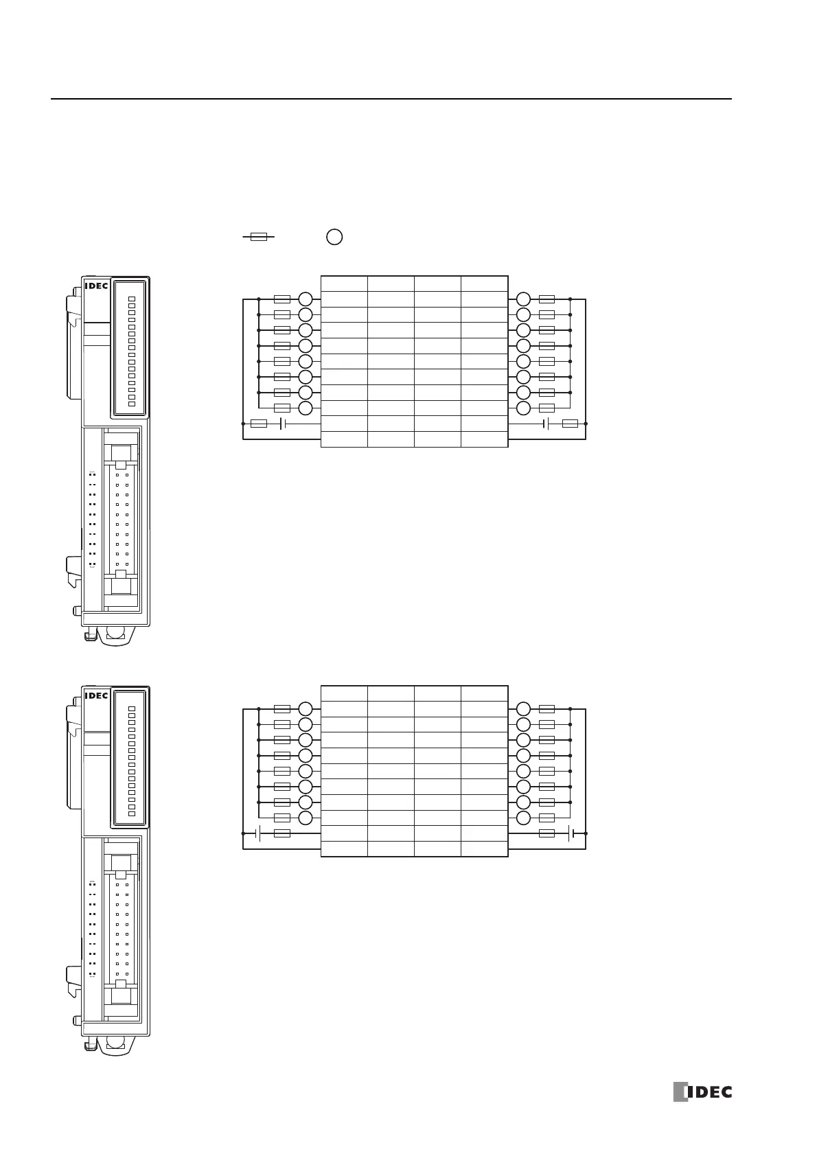
■ FC6A-T16K3, FC6A-T16P3
Terminal block types Applicable connector: FC4A-PMC20PN02
The two COM(+) and COM(-) lines are each connected in the module.
The two +V and -V lines are each connected in the module.
For wiring precautions, see "Input/Output Wiring" on page 3-18.
For the connector cable, see "Cables" on page A-14.
FC6A-T16K3
Insert a fuse that corresponds to the load.
*1 24V DC for products with a version number lower than V400. For details on the version number of
modules, see "Checking the Version Number" on page 2-1.
FC6A-T16P3
Insert a fuse that corresponds to the load.
: Fuse : Load
L
Tr.OUT
0
1
2
3
4
5
6
7
10
11
12
13
14
15
16
17
FC6A-T16K3
20
19
2
1
18
20 Q0
Q1
Q2
Q3
COM(-)
Q4
Q5
Q6
16
14
4
+V
2
12
10
8
6
Q7
17
19 Q10
Q11
Q12
Q13
COM(-)
Q14
Q15
Q16
15
13
3
+V
1
11
9
7
5
Q17
Terminal No.
I/O
Terminal No.
I/O
L
L
L
L
L
L
L
L
-
+
L
L
L
L
L
L
L
L
-
+
12/24V DC 12/24V DC
Tr.OUT
0
1
2
3
4
5
6
7
10
11
12
13
14
15
16
17
FC6A-T16P3
20
19
2
1
18
20 Q0
Q1
Q2
Q3
COM(+)
Q4
Q5
Q6
16
14
4
-V
2
12
10
8
6
Q7
17
19 Q10
Q11
Q12
Q13
COM(+)
Q14
Q15
Q16
15
13
3
-V
1
11
9
7
5
Q17
Terminal No.
I/O
Terminal No.
I/O
L
L
L
L
L
L
L
L
-
+
L
L
L
L
L
L
L
L
-
+
24V DC 24V DC

 Loading...