3: I
NSTALLATION
AND
W
IRING
3-38 FC6A S
ERIES
MICROS
MART
U
SER
’
S
M
ANUAL
FC9Y-B1722
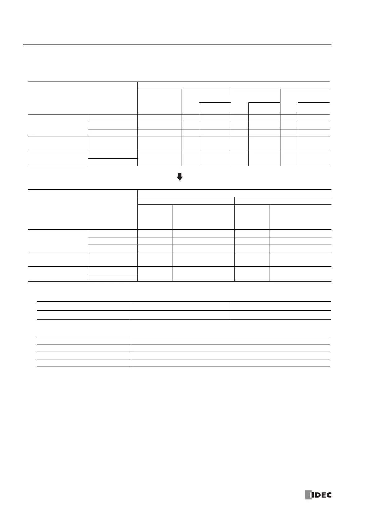
Connecting Modules to the CPU Module
The internal power supply current that can be supplied from the CPU module to the expansion modules on the basic expansion
side, HMI module, cartridge base module, and cartridges is as follows.
*1 The number of modules that can be connected on the basic expansion side does not include the expansion interface module (expander). When
using the expansion interface module (expander), add the following current.
*2 Only the following number of communication modules can be connected to the CPU module, regardless of the internal power supply current
that can be supplied from the CPU module.
*3 Only an analog I/O cartridge can be connected.
*4 When an expansion interface remote master module (FC6A-EXM1M) is connected to the basic expansion side, a maximum of five modules can
be connected on the basic expansion side.
*5 The internal power supply for the internal 5 V line is used to run the expansion modules (basic expansion side), the HMI module, and the
cartridges. Calculate the total current that is used by the modules and ensure that the limit is not exceeded. Use caution because the upper
limits differ with expanded ambient operating temperatures (-25 to -10°C and 55 to 65°C). For details, see "Internal Power Supply Current of
the Modules and Cartridges" on page 3-39.
*6 The internal power supply for the internal 24 V line is used to drive the output module relays and transistors. Calculate the total current when
the outputs are simultaneously ON with the following values as the current per output and ensure that the limit is not exceeded. Use caution
because the upper limits differ with expanded ambient operating temperatures (-25 to -10°C and 55 to 65°C).
• Relay output: 6 mA/point
• Transistor output: 1.5 mA/point
Connecting Modules to the Expansion Interface Remote Slave Module
A maximum of seven expansion modules can be connected on the basic expansion side, regardless of the internal power supply
current that can be supplied from the expansion interface remote slave module.
CPU Module
Maximum Number of Modules That Can Be Connected to the CPU Module
Expansion
Modules
(basic expansion
side)
*1
HMI Module
Cartridge Base
Module
CPU Module Unit
Cartridges Cartridges Cartridges
All-in-One CPU module
16-I/O type 4
*2
11
*3
――― 1
24-I/O type 7
*2
11
*3
――― 1
40-I/O type 7
*2
11
*3
――― 2
CAN J1939 All-in-One CPU
module
40-I/O type 7
*2
11
*3
――― 2
Plus CPU module
Plus 16-I/O type
7
*2*4
1112――
Plus 32-I/O type
CPU Module
Internal Power Supply Current That Can Be Supplied from the CPU Module
Internal 5 V Line Total
*5
Internal 24 V Line Total
*6
Ambient
Operating
Temperature
(-10 to 55°C)
Expanded Ambient
Operating Temperature
(-25 to 10°C, 55 to 65°C)
Ambient
Operating
Temperature
(-10 to 55°C)
Expanded Ambient
Operating Temperature
(-25 to 10°C, 55 to 65°C)
All-in-One CPU module
16-I/O type ≤ 695 mA ≤ 347 mA ≤ 126 mA ≤ 63 mA
24-I/O type ≤ 890 mA ≤ 445 mA ≤ 167 mA ≤ 83 mA
40-I/O type ≤ 1,070 mA ≤ 535 mA ≤ 270 mA ≤ 135 mA
CAN J1939 All-in-One
CPU module
40-I/O type ≤ 960 mA ≤ 480 mA ≤ 270 mA ≤ 135 mA
Plus CPU module
Plus 16-I/O type
≤ 1,070 mA ≤ 535 mA ≤ 350 mA ≤ 175 mA
Plus 32-I/O type
Module Type Model Internal 5 V Line Current
Expansion interface module (expander) FC6A-EXM2, FC6A-EXM24 20 mA
Module Type Maximum No. of Modules (Total on Basic Expansion and Expansion Interface Sides)
All-in-One CPU module 3
CAN J1939 All-in-One CPU module 3
Plus CPU module 15

 Loading...